


1-800-892-3986 IS8444
Pg 28 of 28
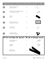
No Incluido
Non incluse
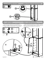
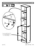
Parte superior de la unidad
Haut du meuble
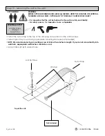
Paso 13: montaje de la unidad en la pared.
Étape 13 – montage de l’unité au mur.
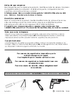
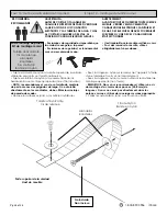
ADVERTENCIA:
ANTES DE CORTAR O TALADRAR EN
CUALQUIER SUPERFICIE DE PARED, VERIFIQUE
LA UBICACIÓN DE LOS CONDUCTOS
ELÉCTRICOS Y LAS TUBERÍAS DE AGUA Y GAS.
AL CORTAR CUALQUIERA DE ESTAS, SE
PODRÍAN OCASIONAR LESIONES GRAVES.
• Por razones de seguridad es imperativo que
la unidad se asegure a la pared.
• Por razones de seguridad, es fundamental
usar una escalera de mano.
AVERTISSEMENT :
AVANT DE COUPER OU PERCER TOUTE SURFACE
MURALE, VÉRIFIEZ L’EMPLACEMENT DES
CANALISATIONS ÉLECTRIQUES, SANITAIRES ET
DE GAZ. DES BLESSURES GRAVES POURRAIENT
SURVENIR SI L’UNE DE CES CANALISATIONS
ÉTAIT SECTIONNÉE.
• Il est impératif que le meuble soit fixé au mur.
• Pour des raisons de sécurité, utilisez
obligatoirement unescabeau.
• Sujete el cinturón de nylon a la parte superior de la unidad,
utilizando una junta y el tornillo antivuelco.
• Sujete el cinturón de nylon a la pared utilizando las
herramientas de montaje apropiadas (no están incluidas).
•
NOTA: recomendamos el uso de un tornillo de montaje
de por lo menos dos pulgadas de largo. Si no atornilla
directamente en los montantes, debe utilizar los anclajes
de pared adecuados.
• Aplique los adhesivos (H16) a los orificios inutilizados.
• Fixez la sangle en nylon sur le dessus de l’appareil à l’aide
d’une rondelle et de la vis anti-basculement.
• Fixez la sangle en nylon au mur en utilisant le matériel de
montage approprié (non fourni).
•
REMARQUE : Nous vous recommandons d’utiliser une vis
de montage d’au moins deux pouces (50,8 mm) de
longueur. Si vous ne vissez pas directement dans les
poteaux muraux, utilisez des ancrages muraux appropriés.
• Collez les autocollants (H16) aux trous non utilisés.
Tornillo antivolcante
Vis de retenue
Arandelas
Rondelles
Tira de Nylon
Bande en nylon
Tornillo antivolcante
Vis de retenue
Arandelas
Rondelles
Tira de Nylon
Bande en nylon
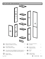
RECOMIENDA
RECOMMANDÉ
Kit de montaje de pared
Kit de montage mural