background image


Version

V1.0

2020.02


Copyright ©  2020    Mainlink All Rights Reserved 

          6     

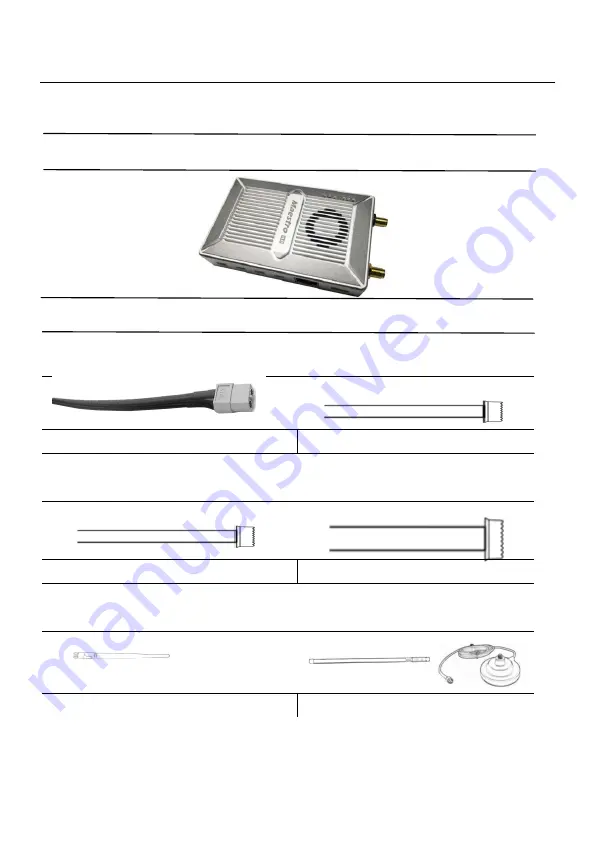
Packing list 

Device      X 2 


Accessories 

2Pin    XT30 cable 

X 2 

3Pin cable 

  X 6 


For Power 

For UART and SBUS 

4Pin cable 

X 2 

7Pin cable 

  X 2 


For Ethernet   

For Ethernet and Power_Out 

Antenna 

X 2 

Fiber-glass antenna 

  X 2 


For air unit 

For ground unit 

Summary of Contents for Maestro M52

Page 1: ...Maestro Long range Wireless Transmission System M52 User s Manual V1 1 2020 07 Introduction Installation Guide Instruction...

Page 2: ...of this manual belongs to Shenzhen Mainlink Aero Communication Technology Co LTD No one may make copies without written consent Caution Attention to installation 1 Before power on make sure the anten...

Page 3: ...used is free of other electromagnetic interference 5 When the signal weakens you can improve the effect by changing the heading direction of the antenna Get instructional video In order to use the sys...

Page 4: ...Description 9 Installation 12 Air 12 Ground 12 Quick start 14 M52 CODEC module MF05 15 M52 with Mission Planner 16 Improve RC controller distance through SBUS 20 Maestro Assistant 22 Interface of Mae...

Page 5: ...Version V1 0 2020 02 Copyright 2020 Mainlink All Rights Reserved 5 System Operation 32 Specification 33 FAQ 35...

Page 6: ...ights Reserved 6 Packing list Device X 2 Accessories 2Pin XT30 cable X 2 3Pin cable X 6 For Power For UART and SBUS 4Pin cable X 2 7Pin cable X 2 For Ethernet For Ethernet and Power_Out Antenna X 2 Fi...

Page 7: ...MF05 And the switching cable is in the accessory box For more information please refer to the relevant section below There are two UART port UART1 and UART2 Two protocols Mavlink and Transparent are s...

Page 8: ...o 34km LOS OFDM Video interface Data interface Ethernet 3 UART TTL RS232 SBUS Hopping Fixed Frequency Frequency Band Fixed user defined 800MHz 1 4GHz Hopping automatic Working mode BW Air unit can be...

Page 9: ...off Wireless link is lost 3 Status Indicator LED Pattern Blink only in booting Description Blink 2 times Initialization OK Frequency is 1 4G Blink 1 time Initialization OK Frequency is 800M Blink 3 t...

Page 10: ...T TX O 3 R RX I 4 R RX I 5 G GND I O 6 G GND I O 7 V 12V DC output Maximum current 1A O 6 Ethernet Number Character Description Input Output 1 T TX O 2 T TX O 3 R RX I 4 R RX I 7 Two SMA antenna inte...

Page 11: ...G GND I O 2 R RXD from external to M52 I 3 T TXD from M52 to external O 13 UART1 Number Character Description Input Output 1 G GND I O 2 R RXD from external to M52 I 3 T TXD from M52 to external O 14...

Page 12: ...t of M52 Connect UART1 to flight control If you need to control the drone with RC please connect SBUS_OUT of M52 to flight control SBUS IN Attention If your gimbal only has HDMI SDI AV interface pleas...

Page 13: ...Connect to the Ground Station The M52 ground unit can be connected to the Ground Station with ethernet or UART Get Video You can get video via RTSP and decode the video with video decoding software su...

Page 14: ...R LED will be solid green Any question please refer to the FAQ It takes 15 seconds to start up After the system starts the wireless transmission can be established 3 Using PC to get video from etherne...

Page 15: ...a page please input the following address rtsp 192 168 1 36 554 stream0 You can get video after click play M52 with CODEC module MF05 If your gimbal has a HDMI SDI AV interface you can add CODEC modul...

Page 16: ...air and ground cable connection is finished Power on the system 3 Install Mission Planner to your computer 4 Set the IP address of the computer Open Network and Internet setting Select Internet Protoc...

Page 17: ...2 Copyright 2020 Mainlink All Rights Reserved 17 5 Get data There are three methods to get data from M52 ground unit using Mission Planner UDP port via Ethernet TCP port via Ethernet UART COM 5 1 Get...

Page 18: ...ight data 5 2 Get data from TCP port Open Mission Planner select TCP click the connect button it will bring up a new window Listen port fill in the blank with IP 192 168 1 236 remote port is 5760 If t...

Page 19: ...eserved 19 Open Mission Planner select COM Please check the COM number and the right baud rate click the connect button Mission Planner will get flight data 6 Get video When you open the Mission Plann...

Page 20: ...e gimbal please use your own gimbal RTSP address Improve RC controller distance through SBUS 1 Connect air unit SBUS_OUT to flight controller RC IN Using the SBUS cable in the accessory box to connect...

Page 21: ...ver to the ground unit Using the SBUS cable in the accessory box to connect the ground unit to the RC receiver Attention The SBUS_IN port of ground unit is input The maximum of 5V output current is 1A...

Page 22: ...on 1 Information display display status information for the M52 2 UART COM select Select the right COM number of the computer to connect M52 If you want to change to another COM please click the Refre...

Page 23: ...u needed and click Set button to complete setup Click the Get button to get current baud rate 12 Select hopping mode There are two mode to be selected Hopping Fixed Choose the mode you needed and clic...

Page 24: ...onfigures M52 Before configuration please connect the UART1 to computer via UART TTL to USB converter Select the right COM and baud rate Click open button 2 Read current parameter After step1 click Re...

Page 25: ...power to choose In order to avoid affecting other devices please select the appropriate transmission power The specific RF power values are as follow 1 Low 20dBm 2 Mid 27dBm 3 High 32dBm 3 4 Hopping...

Page 26: ...int Mode and Repeater Mode Only the air unit of M52 need to be set The ground unit can synchronize automatically In Repeater mode the air unit can be set to TX transmitter or Repeater Point to Point R...

Page 27: ...2 168 1 200 The ground is 192 168 1 236 In Repeater mode TX is 192 168 1 200 Repeater is 192 168 1 201 If you change the device to another IP address please access the web UI through the new IP If you...

Page 28: ...ved 28 Login After you enter IP address in the browser you will see the Welcome page Default username is admin password is 123456 Then you can login Settings In Air setting page user can change air IP...

Page 29: ...er can change Gateway Default 192 168 1 1 User can change Uart1 Baudrate 9600 14400 19200 57600 115200 128000 User can change Default 115200 Uart2 Baudrate 9600 14400 19200 57600 115200 128000 VBR Use...

Page 30: ...Version V1 0 2020 02 Copyright 2020 Mainlink All Rights Reserved 30 Wireless Parameter setting User can change wireless parameter on Wireless Parameter setting page You can refer to the table below...

Page 31: ...g Mode Point to Point Repeater Mode Only the air unit of M52 need to be set The ground unit can synchronize automatically Web UI configuration is the same as Maestro Assistant User can check it in How...

Page 32: ...t on System Operation page While Restore is to restore all parameter to factory settings Reboot is used for system rebooting If user do not change the device IP address it will go to the Login page af...

Page 33: ...width 3MHz 5MHz 10MHz 20MHz Modulation OFDM EIRP 32dBm 1dB Sensitivity 92dBm Range 34km 1 Bit rate 30Mbps 20MHz Power Range DC 9 28V Power consumption 8 5W Interface Antenna SMA 2 Power XT30 UART TTL...

Page 34: ...ical Gain Air 2 5dBi Ground 10dBi SWR 2 0 Environment Work temperature 40 70 Storage temperature 40 85 Humidity 5 95 non condensing Appearance Size 112 X 63 5 X 19 mm weight 143g 1 The distance is tes...

Page 35: ...ght is OK But no data output Solutions 1 Check the UART cable wiring order 2 Check the UART baud rate 3 Please contact our company s after sales service 4 Description The ground unit can t output RTSP...

Reviews: