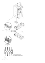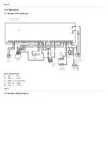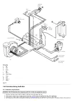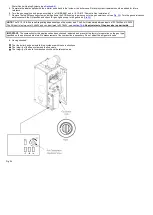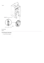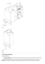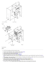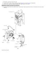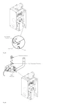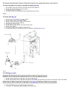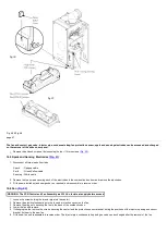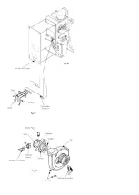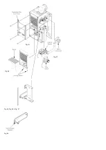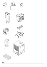
Fig. 49 & Fig. 48
page 47
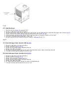
The fan and venturi, gas valve, injector pipe, condensate trap, fan protection sensor, spark and sensing electrodes can be accessed and changed
on the removal of the airbox door panel.
1. Remove the airbox door panel by loosening the four 1/4 turn screws (
).
15.5 Spark and Sensing Electrodes
1. Disconnect all three leads from tabs.
Spark
- Opaque cable
Earth
- Green/Yellow cable
Sensing - White cable
2. Remove the two screws securing each of the electrodes to the combustion box door and remove the electrodes.
3. Fit the new electrodes (and new gasket, as required) and reassemble in reverse order.
)
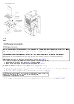
WARNING: The PCB Control and Fan Assembly are 325 Vdc. Isolate at supply before access.
1. Loosen the screw holding the injector pipe into the venturi.
2. Remove the electrical connections to the fan and protection sensor on the fan.
3. Remove the wing nuts securing the fan to the base of the combustion box.
4. Lower the fan and remove.
5. If changing the fan remove the screws securing the venturi and fan protection sensor bracket, noting the positions of the injector opening and sensor
bracket, fix them to the new fan.
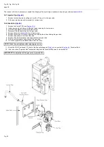
6. Fit the new fan and reassemble in reverse order. The injector pipe, condensate trap and gas valve can be changed after the removal of the fan.
Summary of Contents for Main Heat 12
Page 8: ...Fig 3 Fig 4 Fig 5 Fig 6...
Page 38: ...Example 1 Example 2 Example 3...
Page 40: ...Fig E Fig F...
Page 51: ...Fig 31 Fig 32 Fig 33...
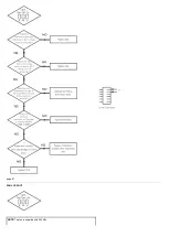
Page 55: ...Fig 35 Fig 36 page 39 12 2 Checking the Combustion 1 Follow the flow chart opposite...
Page 56: ......
Page 63: ...Fig 45 Fig 46...
Page 66: ......
Page 69: ...Fig 55 Fig 56 Fig 57 Fig 58...
Page 72: ...page 52...
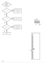
Page 74: ...page 54...
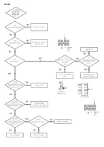
Page 75: ...DRY FIRE...
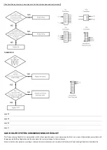
Page 76: ...page 55 IGNITION LOCKOUT...
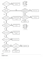
Page 77: ...page 56 OVERHEAT LOCKOUT...
Page 78: ...page 57 FAN LOCKOUT NOTE The fan is supplied with 325 Vdc...
Page 80: ...warranty This does not affect the customer s statutory rights page 62...
Page 82: ...page 63...

