background image


44 

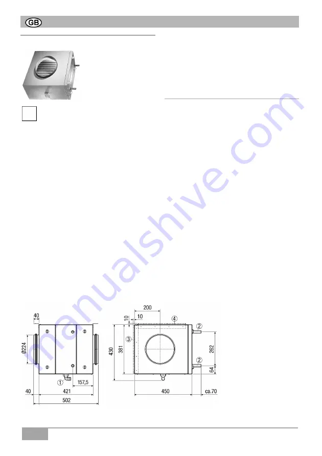
10.2 EW-K 225 brine register 


Important notes 

 Installation work may only be carried out by 

authorised specialists. 

 Take into account the planning documents 

prepared by the engineering office and the 
regulations valid where you are. 

 Take the Technical data listed in Chap- 

ter 13 into account. 

  On-site work (run-off, floor construction, 

etc) must all have been completed before 
installation, as the EW-K 225 cannot be 
moved again once the ducting is 
connected. 

 Insulate the outside air ducts and brine 

ductings


to prevent vapour diffusion for 

energy-usage reasons and to prevent a 
build up of condensation. 

 If installation is fitted outside the thermally 

insulated building envelope, supply and 
exhaust air ducts must also be insulated in 
the cold area. 


 Additional insulation material should be 

used to insulate fixing cuffs. This prevents 
the build up of condensation. 

 Insulate the wall feedthroughs of the out-

side air ducts and brine ductings, in order 
to exclude the possibility of a build-up of 
condensation. 


10.2.1 Connections and dimensions 

 Make sure that there can be no build up of 

surface condensation with roof outlets.  

 Insulate the ventilation ducts with roof 

outlets. 

 In order to avoid any smells, there should 

be sufficient space between the outside air 
inlet for the EW-K and the sewerage vent 
on the roof. 

 The air filter can be mounted on the left or 

right, depending on the installation position 
(

 Chapter 6.2, Changing the air filter). 


NOTICE 

Dirt build-up on unit compo-
nents during building work. 

 Only commission the unit once 

all building work has been 
completed. 

NOTICE 

Build up of condensation on 
the heat exchanger 

 Drain off the condensation 

correctly through a 
condensation run-off with 
siphon. 


1


Condensation drain, 3/4" 

2


Brine connection  

   Ø18 mm (forward and 
   return flow) 
3


Wall-mounting bracket  

4


Ceiling mounting 

 bracket 


Summary of Contents for EW-S

Page 1: ...changer with controller and accessories changeur g othermique saumure avec commande et accessoires EW S EW K 225 EW Z EW D EW G Montage und Betriebsanleitung Mounting and Operating instructions Instru...

Page 2: ...8 5 berpr fung der Rohre 11 8 6 Mechanische Verbindungen 11 8 7 Druckpr fung 11 8 8 Rohrverlegung 12 8 9 Anschlussplan 14 8 10 Sole Umw lzpumpe 14 9 Installationsvorbereitungen 15 9 1 Transport 15 9...

Page 3: ...ichtige Informationen zum Thema Symbol f r Handlungsauffor derungen Hier werden Sie zum Handeln aufgefordert F hren Sie die angegebenen Anwei sungen der Reihe nach aus 3 3BProduktinformationen Sole Er...

Page 4: ...4 D...

Page 5: ...emperaturf hler 3 vor dem EW K 225 misst die Au enlufttemperatur Temperatur f hler 10 nach dem EW K 225 misst die vorerw rmte Au enlufttemperatur Sinken die Temperaturen am F hler 3 und 10 unter einen...

Page 6: ...ten Setzen Sie den Sole Erdw rmetauscher sofort au er Betrieb wenn Sie Sch den oder Fehler feststellen die Personen oder Sachen gef hrden k nnen Verhindern Sie bis zur v lligen Instandsetzung eine wei...

Page 7: ...rundanzeige zur ck Die Beleuchtung schaltet nach weiteren 2 Minuten aus 5 1 23BBedienermen Dr cken Sie Taste um die Steuerung einzuschalten Im Display erscheint f r ca 10 Sekunden die Versionsnummer d...

Page 8: ...Dr cken Sie Taste Die Steuerung EW S schaltet aus Die Au enluft wird nun direkt ohne Tempe ratur nderung an das L ftungssystem weitergeleitet 6 6BReinigung Wartung 6 1 24BSicherheitshinweise Schalten...

Page 9: ...BKondensatabfluss und Siphon reinigen Schalten Sie das EW System an der Steu erung EW S und dann die Netzsicherung aus Entfernen Sie den Luftfilter EW F Kapitel 6 2 Entfernen Sie Ablagerungen in der K...

Page 10: ...berfl che zuflie ende W rme menge abnimmt sollte die Verlegetiefe zwischen 1 2 m und 1 5 m liegen In dieser Tiefe herrschen im Jahresverlauf zwischen 7 C und 13 C Dieses Temperaturniveau kann sehr eff...

Page 11: ...len k nnen Unfallgefahr Da besonders bei gr eren Durchmessern erhebliche Kr fte frei werden ist entsprechend vorsichtig vorzugehen 8 5 32B berpr fung der Rohre Die Rohre sind vor dem Einbringen auf ev...

Page 12: ...m V Entzugs leistung Boden Q Leitungsl nge 2 m PE Rohr pro m Kollektorfl che trockener nichtbindiger Boden Bindiger Boden feucht Wasser ges ttigter Sand Kies 10 W m 20 W m 40 W m m h W m m m 100 533 1...

Page 13: ...m 1 5 fachen Wert zu unterziehen Die Funktion aller Bauteile ist zu berpr fen und die Pr fbescheinigung sind dem Betreiber auszuh ndigen Installationshinweise Erdkollektoren d rfen nicht berbaut werde...

Page 14: ...rt diesen Sole Massenstrom Zum Beispiel f r ein Raumluftsystem mit einem Luftvolumenstrom von 250 m h ab eingestellter Drehzahlstufe II T2 Temperatursensor Au enluft Luft volu men strom V Ent zugs lei...

Page 15: ...en in Kapitel 8 Bringen Sie das Sole Register EW K 225 am Aufstellungsort an Bringen Sie den Kondensatabfluss an f llen Sie den Siphon mit Wasser auf Schlie en Sie die L ftungskan le DN 224 an bringen...

Page 16: ...Dies vermeidet Kondensatbildung D mmen Sie die Wanddurchf hrungen der Au enluft und Soleleitung so dass Kondensatbildung ausgeschlossen ist 10 2 1 57BAnschl sse und Abmessungen Stellen Sie bei Dachdur...

Page 17: ...nsatabfluss stutzen zur Vermeidung von Schwitz wasser Gie en Sie nun Wasser in den Konden satabfluss im Sole Register EW K 225 Pr fen Sie den Anschluss auf Dichtheit Setzen Sie den G4 Luftfilter in da...

Page 18: ...Ablauf KFE Hahn zum Entleeren der Anlage 13 Halterung Anschluss Ausdehnungsgef Technische Daten EW Z Obere Anschl sse IG Untere Anschl sse IG Pumpe Wilo ST 15 6 eco 3 Nennstrom Pumpe max 5 A Anschlus...

Page 19: ...die Pumpengruppe in der Unterschale ein und verbinden Sie diese mit dem Rohrleitungsnetz Bringen Sie die Ausdehnungsgef An schlussleitung 11 am Manometer 5 an Montieren Sie Halterung 13 und das Ausde...

Page 20: ...weiligen Kugelhahn ab Stellen Sie die Schwerkraftbremse gem Ihren Anforderungen ein Einstellung 0 Werkseinstellung Schwerkraftbremse in Betrieb Durchstr mung in Flussrichtung Einstellung 45 Schwerkraf...

Page 21: ...cher Anschluss GEFAHR Lebensgefahr durch Strom schlag Schalten Sie bei allen Arbeiten an der elektrischen Einrich tung des EW Systems die Netzsicherung im Sicherungs kasten aus Bringen Sie ein Warnsch...

Page 22: ...ren Sie vor und nach dem EW K 225 die beiden Temperatursensoren PT 1000 zur Erfassung der Au enlufttemperatur Die Sensoren liegen der Steuerung EW S bei Beachten Sie die Mindestabst nde der Temperatur...

Page 23: ...u empfehlen wenn die Anlage in einer warmen Region mit milden Wintertemperaturen installiert ist eine g nstige Bodenbeschaffenheit Ausrichtung oder Lage vorliegt ein WP Kompaktger t nach dem EW K 225...

Page 24: ...mpe Stellen Sie die zur Anlagengr e passende Pumpleistung wie folgt ein Schalten Sie das System ein Entfernen Sie die D mmschale der Pumpengruppe Lesen Sie an der Skala der Durchfluss mengenanzeige de...

Page 25: ...rages und f r die Energiebilanzierung herangezogen Diese Einstellung hat keinerlei Auswir kung auf die Systemleistung F rder menge der Pumpe P7 Heizstab ausgeschaltet freigegeben Hier l sst sich der H...

Page 26: ...apitel 10 6 Beim Einbau T1 und T2 nicht vertau schen T1 vor dem EW K 225 und T2 in Luftrichtung nach dem EW K 225 installieren P6 Volumenstrom P6 Volumenstrom 220 m h Dr cken Sie um die Volumenstrom a...

Page 27: ...nzeige Beachten Sie unbedingt die Angaben in Kapitel 10 P15 WP Betrieb ausgew hlt Dr cken Sie Taste P15 WRG Betrieb ausgew hlt Dr cken Sie P15 WRG Betrieb gesetzt Dr cken Sie und Taste Es erscheint di...

Page 28: ...r Temperatursensor PT 1000 Digitale Ausg nge 2 Nennstrom f r EHZ max 5 A Pumpe Bemessungsspannung 230 V Bemessungsfrequenz 50 Hz Nennstrom Pumpe max 5 A Anschluss RS 232 Schnittstelle 1 Display 2 Zeil...

Page 29: ...es Wasserhaushaltsgesetzes WGH Entsorgen Sie diese stets umweltgerecht gem den in Ihrem Land geltenden Bestimmungen Sicherstellen dass keine wassergef hr denden Stoffe den Boden verunreinigen oder in...

Page 30: ...ting 39 8 8 Laying ducts 40 8 9 Connection plan 42 8 10 Brine circulation pump 42 9 Installation preparations 43 9 1 Transport 43 9 2 Requirements at the EW K 225 installation site 43 10 Installation...

Page 31: ...you will find important information about the subject Symbol for requests for action Here you are asked to take action Follow the instructions given in the order stated 3 Product information As a rule...

Page 32: ...32...

Page 33: ...of the EW K 225 measures the outside air temperature Temperature sensor 10 after the EW K 225 measures the preheated outside air tempe rature The pump starts up if the temperatures at the sensor 3 an...

Page 34: ...scover damage or faults that could endanger persons or property Make sure the unit cannot be switched back on until it has been fully repaired Installation is only permitted when carried out by traine...

Page 35: ...tches back to the starting display The lighting switches off after further 2 minutes 5 1 Operator menu Press to switch on the controller The version number appears in the display for approx 10 seconds...

Page 36: ...er off Press The EW S controller switches off Outside air is now fed directly to the ventilation system without any temperature change 6 Cleaning maintenance 6 1 Safety instructions Switch off the EW...

Page 37: ...f and siphon Switch the EW system off at the EW S controller and then switch the mains fuse off Remove the air filter EW F Chapter 6 2 Remove the deposits in the condensation tank and drain tube Flush...

Page 38: ...ume of heat supplied by the earth s surface actually starts to decrease the depth of laying should be between 1 2 m and 1 5 m Temperatures at this depth fluctuate over the year between 7 C and 13 C Th...

Page 39: ...coils note that the ducts may shoot off like springs when the attachment is loosened risk of accident Since considerable forces are released when working with larger diameters proceed with care 8 5 C...

Page 40: ...r volumetric flow V Ground extraction rating Q Ducting length 2 m PE duct per m collector surface dry frictional soil Compact soli damp Water saturated sand gravel 10 W m 20 W m 40 W m m h W m m m 100...

Page 41: ...missioning The function of all components must be checked and the test certificates are to be given to the operator Installation instructions Ground collectors may not be built on top of The surface a...

Page 42: ...that we selected delivers this brine mass flow e g for a room air system with a volumetric flow of 250 m h from a setting of Speed level II or higher T2 Temperature sensor outside air Air volu metric...

Page 43: ...See Planning documents in Chapter 8 Bring the EW K 225 brine register to the installation site Connect the condensation run off and fill the siphon up with water Connect the DN 224 ventilation channe...

Page 44: ...ffs This prevents the build up of condensation Insulate the wall feedthroughs of the out side air ducts and brine ductings in order to exclude the possibility of a build up of condensation 10 2 1 Conn...

Page 45: ...ain hose and the condensation run off connection to avoid condensation Now pour some water into the EW K 225 brine register s condensation drain and check that the connection is water tight Position t...

Page 46: ...r emptying the system 13 Holder Expansion tank connection EW Z technical data Upper connections IG Lower connections IG Pump Wilo ST 15 6 eco 3 Nominal current for pump max 5 A Connection expansion ta...

Page 47: ...Locate the pump assembly in the sub shell and connect it to the ducting network Fit the expansion tank supply pipe 11 to the pressure gauge 5 Install the holder 13 and the expansion tank Check all scr...

Page 48: ...meter Remove the thermometer at the corresponding ball valve Adjust the gravity brake in line with your requirements 0 setting Factory setting Gravity brake in operation flow in flow direction 45 sett...

Page 49: ...nnection DANGER Danger to life from electric shock Switch off the mains fuse at the fuse box when carrying out any work on the EW systems electrical equipment Position a visible warning notice to avoi...

Page 50: ...wo PT 1000 temperature sensors before and after the EW K 225 for recording the outside air temperature The sensors are included with the EW S controller Note the minimum spacings between the temperatu...

Page 51: ...system is installed in a warm region with mild winter temperatures There is an advantageous ground condition direction or position a WP compact unit is installed downstream from the EW K 225 an increa...

Page 52: ...mp Set the pump performance suitable to the system size as follows Switch the system on Remove the pump assembly insulation shell Read off the flow quantity from the scale on the flow quantity display...

Page 53: ...otal yield and for the energy balancing This setting has no effect on the system performance pump flow quantity P7 Heating element switched off on Here the heating element in a downstream EHZ electric...

Page 54: ...nsors Chapter 10 6 Don t transpose T1 and T2 during installation Install T1 ahead of the EW K 225 and T2 after the EW K 225 in the direction of air flow P6 Volumetric flow P6 Volumetric flow 220 m h P...

Page 55: ...n Chapter 10 P15 WP mode selected Press P15 WRG mode selected Press P15 WRG mode set Press and The starting display appears Starting display 12 35 21 01 11 16 C The lighting switches off after approx...

Page 56: ...00 temperature sensors Digital outputs 2 Nominal current for EHZ max 5 A Pump rated voltage 230 V Rated frequency 50 Hz Nominal current for pump max 5 A RS232 interface connection 1 Display 2 lines 16...

Page 57: ...pose of them in an environmentally friendly way in accordance with the applicable regulations in your country Ensure that no substances hazardous to water can contaminate the ground or get into the se...

Page 58: ...accordements par serrage 67 8 7 34B preuve de pression 67 8 8 35BPose du conduit 68 8 9 36BSch ma de raccordement 70 8 10 37BPompe de circulation brine 70 9 9BPr paratifs d installation 71 9 1 38BTran...

Page 59: ...ouverez ici des informa tions importantes sur le sujet Symbole d incitation l action On vous demande ici d agir Suivez les instructions dans l ordre indiqu 3 3BInformations sur le produit Les changeur...

Page 60: ...60...

Page 61: ...saisies et valu es en perma nence 3 2 2 54BFonctionnement La sonde de temp rature 3 situ e devant le EW K 225 mesure la temp rature de l air ext rieur la sonde de temp rature 10 situ e derri re le EW...

Page 62: ...sivement des filtres d origine Remplacez le filtre pour des raisons d hygi ne avant une remise en route faisant suite une immobilisation prolong e Mettez imm diatement l changeur g othermique saumure...

Page 63: ...saumure EW n est pas un climatiseur 5 5BCommande Touches Marche Arr t Plus Minus Enter Le syst me EW est command l aide de la commande EW S D s que le syst me est activ l cran est clair par actionneme...

Page 64: ...pouvez galement arriver P3 avec R glez l heure avec ou Confirmez avec R glez les minutes avec ou Confirmez avec P3 Entr e de la date P3 Date P3 Datum 21 08 11 Appuyez sur la touche ou pour P4 R glez...

Page 65: ...biant 6 3 26BNettoyer EW K En fonction du degr d encrasse ment nous conseillons un nettoyage annuel de l changeur thermique nettoyage int rieur annuel nettoyage semestriel de l coule ment du condensat...

Page 66: ...ol tenir compte par exemple des l ments encastr s des art res de c bles des vacuations d eau Sur le terrain tenir compte par exemple des limites du terrain des constructions de la carrossabilit de la...

Page 67: ...rasser l int rieur Il convient par cons quent de ne retirer les volets de fermeture que lors du montage 8 4 31BParticularit s lors du traitement des couronnes Lors du d roulement des couronnes veiller...

Page 68: ...d air V Capacit de retrait Sol Q Longueur de conduit 2 m gaine PE par m de la surface du collecteur sol sec non coh rent sol coh rent humide sable graviers gorg s d eau 10 W m 20 W m 40 W m m h W m m...

Page 69: ...ion Aucune construction ne doit se trouver au dessus des collecteurs enterr s La surface du sol se trouvant au dessus des collecteurs ne doit pas tre scell e Les gaines PE doivent tre prot g es contre...

Page 70: ...n Wilo ST 15 6 de notre choix assure ce d bit massique de saumure Par exemple pour un syst me air ambiant d un volume de 250 m h d s le niveau de vitesse r gl en position II T2 Sonde de temp rature Ai...

Page 71: ...cf Documents de conception au Chapitre 8 Positionnez la batterie saumure EW K 225 sur le lieu d installation Positionnez l coulement de condensat remplissez le siphon avec de l eau Refermez les gaine...

Page 72: ...isolant Ceci permet d viter la formation de condensat Isolez les passages muraux laissant p n trer l air ext rieur et de saumure pour viter la formation de condensat 10 2 1 57BRaccordements et dimensi...

Page 73: ...d coulement et la tubulure de raccordement du con densat afin d viter la formation de bu e Faites couler de l eau dans l coulement de condensat de la batterie saumure du EW K 225 V rifiez l tanch it...

Page 74: ...et boisseau sph rique pour la vidange de l installation 13 Fixation Raccordement Vase de dilatation Caract ristiques techniques EW Z Raccords sup rieurs IG Raccords inf rieurs IG Pompe Wilo ST 15 6 ec...

Page 75: ...r nage inf rieur et reliez le au r seau de conduits Branchez le conduit de raccordement du vase de dilatation 11 sur le manom tre 5 Montez la fixation 13 et le vase de dilatation V rifiez tous les rac...

Page 76: ...e thermom tre du robinet boisseau correspondant R glez le frein commande par gravit en fonction de vos besoins R glage 0 par d faut frein commande par gravit actif circulation dans le sens d coulement...

Page 77: ...par lectrocution Lors des interventions sur le dispositif lectrique du syst me EW coupez imp rative ment le fusible secteur dans le coffret de fusibles Apposez une plaque signal ti que bien visible m...

Page 78: ...es de temp ratures PT 1000 servant saisir la temp rature de l air ext rieur en amont et en aval du EW K 225 Les sondes sont jointes au jeu de la commande EW S Respectez les distances minimum entre les...

Page 79: ...on chaude pr sentant des temp ratures douces en hiver la nature du sol l orientation ou la situation sont favorables un appareil compact WP est install en aval de l EW K 225 des messages d avis de gel...

Page 80: ...mpe R glez comme suit les performances de la pompe correspondant la taille de l installation mettez le syst me en route retirez la couche d isolation avant du groupe de pompes Lisez le d bit indiqu pa...

Page 81: ...e pour le calcul du rendement total et pour le bilan nerg tique Ce r glage n a aucune influence sur la performance du syst me d bit de la pompe P7 Cartouche chauffante d sactiv e activ e La cartouche...

Page 82: ...de la diff rence de temp rature ou sur pour P6 P5 L annulation de la diff rence de temp rature est effectu e P5 Temp Abgleich ist ausgef hrt Appuyez sur Appuyez sur la touche pour P6 ou pour renouvel...

Page 83: ...er une interro gation nouveau ou sur pour P9 P9 et P10 P13 Messages de protection antigel P9 Afficher les messages P9 Meldungen zeigen Appuyez sur pour afficher le premier message de protection antige...

Page 84: ...r kurzschl Temperatur2 EWT Erreur Court circuit Temp 2 EWT La sonde de temp rature ou son c ble de raccordement est d fectueux ou mal branch Fehler im Modul error sys XX Erreur dans Module error sys X...

Page 85: ...ection de l environnement nonc es au Chapitre 15 1 D posez le raccord de protection ouvrez le robinet boisseau d vacuation et vidanger la batterie saumure EW K 225 Fermez le robinet boisseau d vacuati...

Page 86: ...nt conform ment la r glementation en vigueur dans votre pays S assurer qu aucune substance mettant en danger la qualit de l eau ne contamine le sol ou ne s coule dans les canalisations 15 2 50BEmballa...

Page 87: ...87...

Page 88: ...Maico Elektroapparate Fabrik GmbH Steinbeisstr 20 78056 Villingen Schwenningen Germany Service 49 7720 694 447 technik maico de s 11_E 10 W S D _ 11 _10 3 LF 0_R 00 0 1 7 6 5 1 018...

Reviews: