8 Installation and commissioning
29
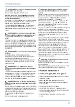
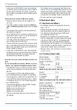
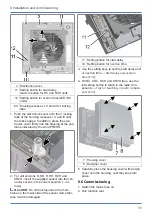
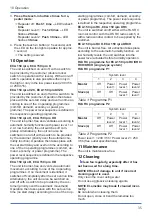
The foam strip must be fitted to the ECA
150 ipro H and KH, so that the units do not
draw in any infiltration air from outside.
4. For an electrical surface-mounted connection,
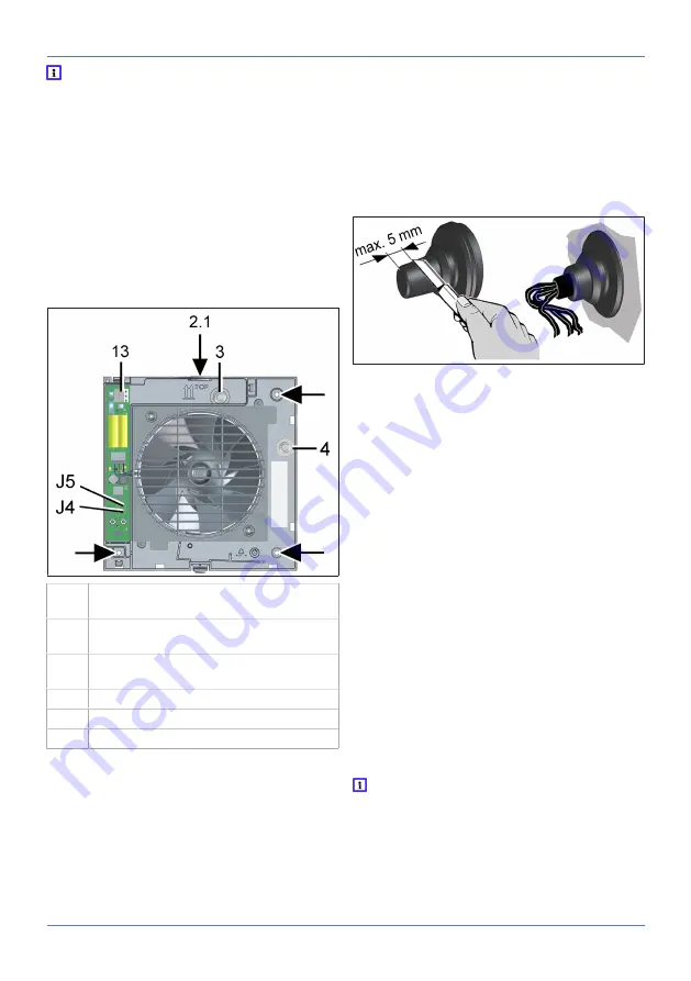
drill the housing segment [2.1] (→ following
figure) (Ø 11 mm).
8.2 Housing installation
NOTICE Damage to unit/functional problems
in the event of rubbing impeller.
Do not fit flange sleeve either twisted or crushed.
Make sure that the surface is flat.
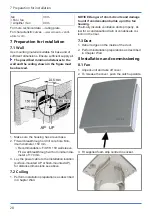
1. Insert housing into wall breakthrough/wall
sleeve (TOP).
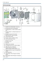
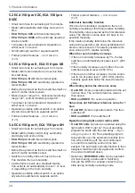
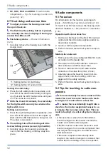
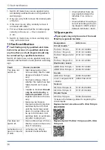
2.1 Housing segment – surface-mounted
connection
3 Cable grommet – flush-mounted connec-
tion
4 Cable grommet – surface-mounted con-
nection
13 Spring terminal
J4 Jumper J4
J5 Jumper J5
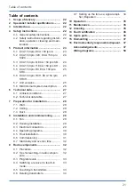
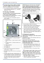
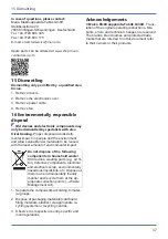
2. Align housing horizontally and mark the 3
dowel holes → arrows.
3. Drill dowel holes with a Ø of 6 mm and insert
dowels.
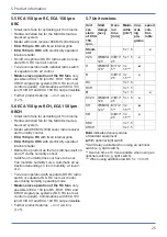
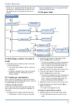
4. Carefully press the upper cable grommet out
of the housing and remove it. Alternatively, for
electrical surface-mounted connection, leave
the upper cable grommet in the housing and
remove the side cable grommet from the
housing.
NOTICE Danger of short-circuits / damage to
the unit. Water will penetrate if the power
cable is incorrectly fed into the fan housing or
if the cable grommet is not fitted correctly.
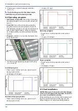
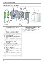
Cut off the cap of the cable grommet so that the
cable grommet tightly encloses the power cable.
Shorten the cap by a
max. of 5 mm
.
Fit cable grommet correctly, seal on site if re-
quired.
5. Insert cable grommet into housing.
6. Guide the power cable into the terminal com-
partment such that the cable grommet fits
around the cable sheathing completely.
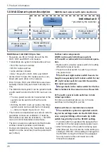
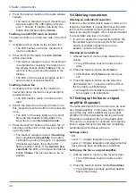
7. Insert housing into wall breakthrough/wall
sleeve and secure with 3 screws. Do not insert
the housing such that it is twisted or crushed.
Make sure you use mounting material which is
sized for the purpose.
8.3 Electrical connection
NOTICE Risk of damage to unit in the event of
short-circuits.
Insulate PE conductor and individual cable cores
that are not required.
Do not touch electric components.
Master-slave operation of RC units is only
possible with similar types of ECA 150 ipro
RC/RCH/KRC/KRCH units.
1. Only lay single cable cores in the fan. To do
this, remove the power cable’s sheathing in
the terminal compartment. Strip single cable
cores to 9 to 10 mm.
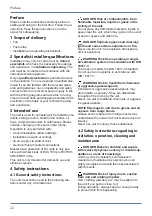
2. Connect power cable to the spring terminal
→ .
The standard model of ECA 150 ipro can be
operated in two levels with double switches.
Without a double switch, the fan can be oper-
ated either at power level 1 or at power level 2
→ switching variants in chapter
.
3. Check the position of the cable grommets.
These must provide a good seal.

