


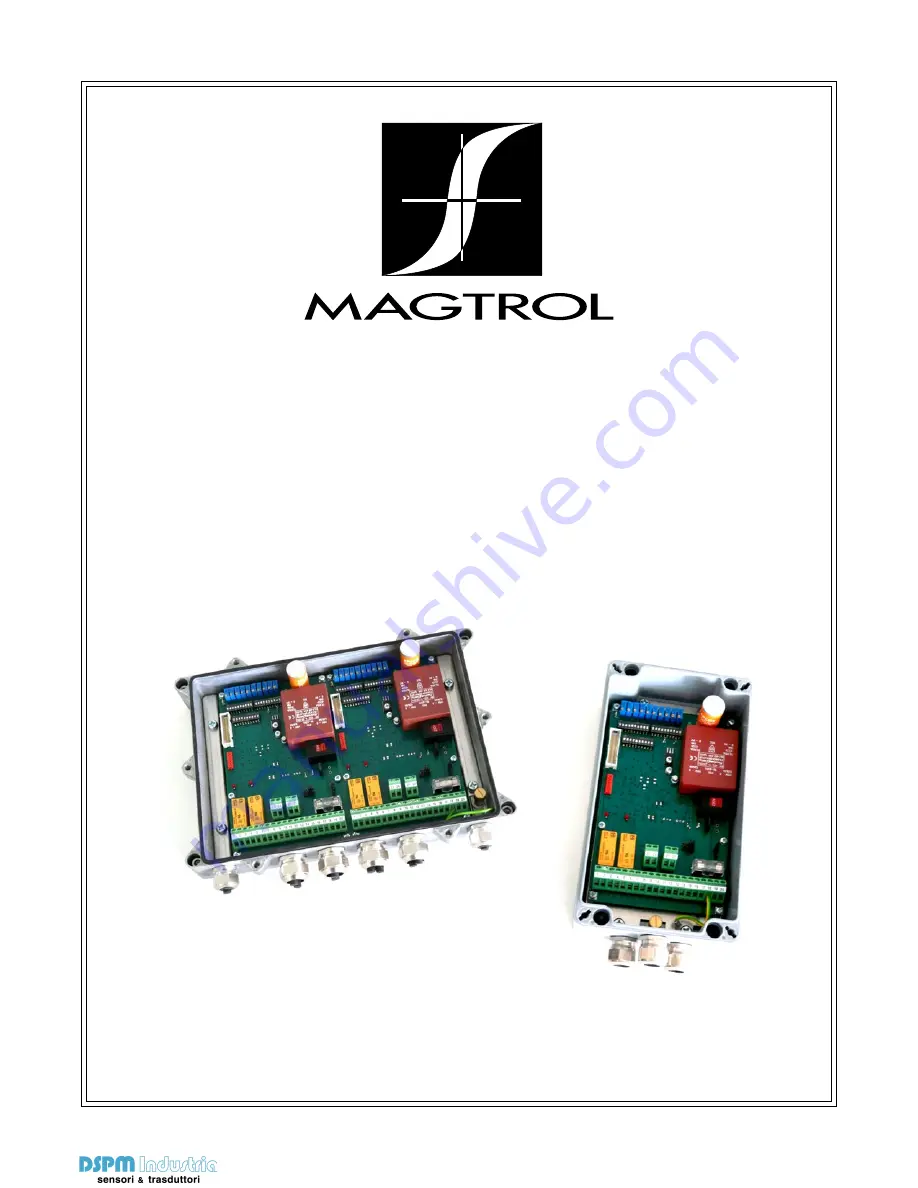
Load Monitoring Units
LMU 212 and LMU 217
User’s manual
Via Paolo Uccello 4 - 20148 Milano
Tel +39 02 48 009 757 Fax +39 02 48 002 070 [email protected] www.dspmindustria.it
Load Monitoring Units
LMU 212 and LMU 217
User’s manual
Via Paolo Uccello 4 - 20148 Milano
Tel +39 02 48 009 757 Fax +39 02 48 002 070 [email protected] www.dspmindustria.it


