oDynamo Development Kit
Quick Installation Guide
Page 2 of 2 (
D998200307-C0
)
i)
Connect the 9-pin DIN serial data leg of the RS-232 / power cable (
1000004111)
to the host.
ii)
Connect the other signal leg of the cable to the device’s
RS-232 and Power Port [J1]
.
iii)
Connect the power supply (
1000004941
) to the power connector on the cable’s Y junction.
b)
To use the
USB Device Port [J3]
to communicate with the host using USB:
i)
Connect the USB cable (
22350300
) to the device’s
USB Device Port [J3]
.
ii)
Connect the other end of the cable to the host’s USB port.
iii)
Connect the power-only cable (
1000003906
) to the device’s
RS-232 and Power Port [J1]
.
iv)
Connect the other end of the power-only cable to the power supply (
1000004941
).
c)
To use the
Ethernet Port [J4]
to communicate with the host using TCP/IP:
i)
Connect the Ethernet cable (
71900032
) to the device’s
Ethernet Port [J4]
.
ii)
Connect the other end of the Ethernet cable to a network switch on the same network segment
as the host, or appropriate network drop on the LAN.
iii)
Connect the power-only cable (
1000003906
) to the device’s
RS-232 and Power Port [J1]
.
iv)
Connect the other end of the power-only cable to the power supply (
1000004941
).
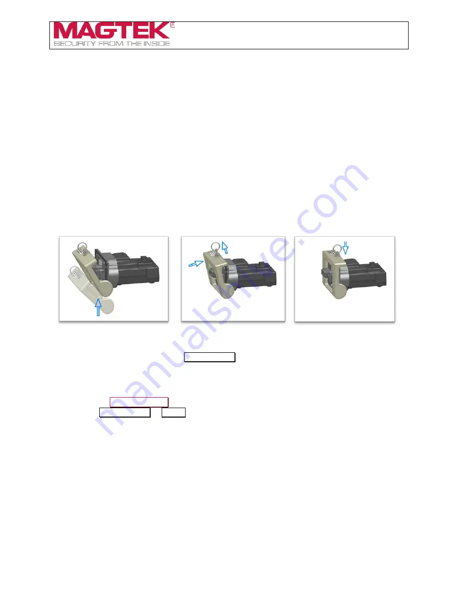
7)
Engage the device’s dismount switches by connecting the clip-on dismount switch lock
1000005104
:
8)
Connect the power supply (
1000004941
) to a properly grounded AC socket-outlet.
9)
Make sure the power supply LED turns on and that the device’s General Status LED is blinking
yellow to show the device is in the
Pre-Activated
state.
10)
oDynamo is now ready for testing and development. See the product documentation and the sample
code / demonstrations / documentation in the SDKs to do the following:
a)
Test the connection between the device and the host.
b)
Send an
Activate Device
command and make sure the device’s General Status LED transitions
from
Pre-Activated
to
Ready
.
c)
Test the device’s card reading capabilities.


