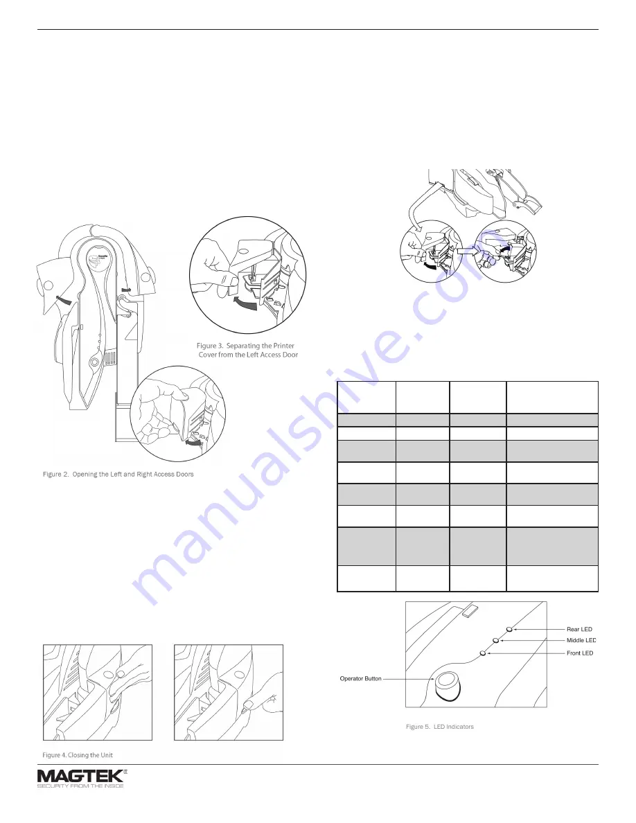
Install Print Cartridge
•
Pull the Printer/Cartridge cover open to expose the Printer/Cartridge.
•
Push the Printer/Cartridge green latch down.
•
Locate the alignment pegs on the Printer/Cartridge and the guide
holes on the Printer Base.
•
Install the Printer/Cartridge on the Printer Base by sliding the
alignment pegs into the guide holes.
•
Raise the green latch to lock the Printer/Cartridge in position.
•
Close the Printer/Cartridge cover.
Troubleshooting/LEDs
The LED indicators are shown in Figure 5. All three LEDs are able to show
three colors: green, red, or amber. Each LED indicator has been assigned a
specific reporting function.
• Front LED: reports MICR read status
• Middle LED: reports path status
• Rear LED: reports unit status
Front LED
(MICR status)
Middle LED
(Path status)
Rear LED
(Unit status)
Description
Amber
Amber
Amber
Unit is initializing
Green
Green
Green
Power on, everything is OK
X
X
Flash Amber
Initializing network con-
nection
Flash Red
X
X
After check read: MICR
read error
Flash Green
X
X
After check read: good
MICR read
Flash Red/
Green
X
X
MICR noise detected (if
enabled): relocate unit
X
Amber
X
Left or right access door
unlatched (if feature is
installed): close and latch
access guides
X
Flash Red
X
Paper jam: remove jam and
hit operator button to clear
Note: More detailed instructions can be found in Excella’s Installation and
Operation Manual (P/N 99875310).
Opening and Closing the Unit
OPENING THE UNIT
•
The Left Access Door, the Right Access Door and the Printer/Cartridge
Cover, shown in Figure 2, can be opened to provide access to the
check path and both scan bars. Open the unit as described as follows:
•
Open the Left Access Door by placing the thumb on the Indent and
the finger(s) on the Tab as shown in Figure 2 and squeezing, and then
gently pull the Door open.
•
Open the Right Access Door, in the same manner, by placing the
thumb on the Indent and the finger(s) on the tab, and squeezing and
then gently pull the guide open.
•
Open the Printer/Cartridge Cover by pulling the Cover from the Left
Door as shown in Figure 3.
CLOSING THE UNIT
•
If the Left Access Door or the Right Access Door has been opened,
close the access door as described below:
•
Push to close the access door (Left or Right) to its normal operating
position (as show in Figure 4).
•
If the Printer/Cartridge Cover is open on the Left Access Door, first
close the printer cover and then close the access door as described in
step 1 above.
•
Push down on the tab of the access door (as shown in Figure 4) If
the tab was not latched, a “click” sound will be heard as feedback to
indicate the access guide is securely closed.
•
The LED indicator will flash if the access door is improperly closed.
MagTek®, MagnePrint®, and MagneSafe® are registered trademarks of MagTek, Inc.
MAGTEK: Registered to ISO 9001:2015 © Copyright 2021 MagTek, Inc. PN D99800048 rev 30 3/21
MagTek
®
Inc., 1710 Apollo Court, Seal Beach CA 90740 | p 562-546-6400 | support 651-415-6800 | f 562-546-6301 | www.magtek.com
Use and LEDs


