Magnum MIG 208 Alu Synergy Manual Download Page 1

MANUAL inverter

semi-automatic WELDING

Model: 

MIG 208 Alu Synergy

Drawings devices in the manual may differ from the original colors. 

Translation of the original instructions. 

with

NOTE: Please use a welder after a very careful reading the manual. 

1. In order to ensure safety should be determined by qualified personnel responsible for installation, 
maintenance, periodic inspection and repair equipment. 
2. In order to ensure safety before working with the machine carefully and with full understanding 
refer to the following instructions. 

3. After reading the following instructions and keep it in a place accessible to other users of the 
device. 

Summary of Contents for MIG 208 Alu Synergy

Page 1: ...careful reading the manual 1 In order to ensure safety should be determined by qualified personnel responsible for installation maintenance periodic inspection and repair equipment 2 In order to ensure safety before working with the machine carefully and with full understanding refer to the following instructions 3 After reading the following instructions and keep it in a place accessible to other...

Page 2: ...2 ...

Page 3: ...g MIG MAG 16 7 2 Fitting wire welding MIG MAG 16 7 3 Inserting the wire electrode 16 7 3 Inserting the wire electrode 16 7 3 Inserting the wire electrode 16 7 4 Connection of protective gas 17 7 4 Connection of protective gas 17 7 4 Connection of protective gas 17 7 5 welding parameters for MIG MAG 17 7 5 welding parameters for MIG MAG 17 7 5 welding parameters for MIG MAG 17 7 6 Practical recomme...

Page 4: ...een built on transistors IGBT providing a minimum of electromagnetic The power source has been built on transistors IGBT providing a minimum of electromagnetic interference low power losses in core systems enabling increased productivity and reliability of the power source Very high efficiency which translates directly into lower power consumption and high switching frequency provide instant adjus...

Page 5: ...nd or serious injury Keep all safety regulations and instructions for future use You can not allow children near the place of operation People with pacemakers take him to work with the device should consult with your doctor Service and repair of equipment They can be carried out by qualified personnel under the terms safety applicable to electrical appliances Processing on their own may alter the ...

Page 6: ... and the scope of the welding work b schedule the execution order of individual welds c prepare a suitable adhesive d prepare adequate protection face and eyes e check the condition of the welding connections and the operating handle f check whether the execution of the welding does not endanger the environment radiation curve the possibility of ignition elements flammable g check whether in the c...

Page 7: ...ar from the welding face her deposition before the arc goes out as well as inflammation of the arc without face protection e Welding without proper grounding of the workpiece f Use makeshift combination of welding equipment f Use makeshift combination of welding equipment g Cause to the floor at the work station was wet slippery uneven contaminated waste previously blocked 3 5 Basic activities aft...

Page 8: ...ELDS MAY BE DANGEROUS Electric current flowing through wires Welding produces electromagnetic field around it Electromagnetic fields can interfere with pacemakers Welding cables should be arranged in parallel as close as possible to each other SPARKS CAN CAUSE FIRE Sparks generated during welding can cause fire explosion and burns unprotected skin SPARKS CAN CAUSE FIRE Sparks generated during weld...

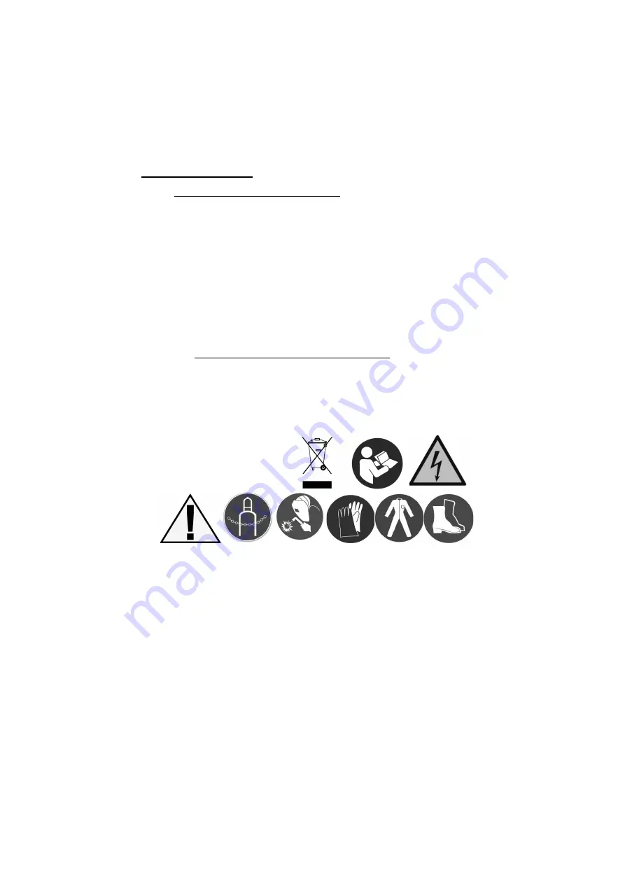
Page 9: ...r other symbols that failure can lead to personal injury or equipment damage The product complies with the requirements of European Union directives Disposal of electrical and electronic equipment see DISPOSAL in this manual Use welding helmet or shield Use welding gloves Wear protective welding obligatory Wear protective welding kneading Secure the cylinder from falling over Risk of electric shoc...

Page 10: ...urrent the output minus 3 Euro slot 4 Jack current output plus 5 cable to change the polarity NOTE WHEN MIG MAG CABLE MUST BE stuck in one of the unit current 6 Near the cable polarity change control socket handle SPOOLGUN Main switch and connector for connecting the protective gas are located on the rear of the machine 1 Display 2 Turn multifunctional button 3 Turn multifunctional button 1 2 3 ...

Page 11: ... MIG MAG manual operation of setting the top dial to be adjusted wire feed speed the lower knob voltage value of the welding current The set value will be shown on the display The value of the welding current appears only during welding While in manual mode MAN You can also select spot While in manual mode MAN You can also select spot While in manual mode MAN You can also select spot welding and t...

Page 12: ...al wire diameter and shielding gas should push for no less than 2 seconds lower the dial until the symbols will appear as below One of the symbols in the group materials will blink Rotating the bottom knob in either direction select the desired symbol of the material no blink Approval of the selection is done by briefly pressing the lower knob Symbol will be displayed only the selected material ot...

Page 13: ...he display will change the shape of the graphic indication of the weld The shape of the convex is the low thermal load in low merging the material Shape intermediate the recommended setting the average fusing the material The shape of the concave is a high thermal load and at a high merging the material LIST synergic programs Ar Use of gas recommended by the manufacturer of wire In the case of sel...

Page 14: ... soft arc results in a wider weld pool and less spatter While the lower inductance produces a stable concentrated arc The height of burning wire after welding burn back Adjusting the range 0 200 ms Gas flow time after welding Adjusting the range 0 5 s To enter the menu for adjusting these parameters press and hold for 2 seconds or two adjustment knobs at the same time Adjustment is done by turning...

Page 15: ...is manual and on the rating plate Check the grounding wire connection device to the mains Make sure the power network can ensure coverage of the power demand for the input of the device under its normal operation Fuse size and parameters of the power cord are given in the technical data of this manual The supply network should have a stable voltage Cross section of the supply lines should not be l...

Page 16: ...sories from the welding torch in the contact tip to the appropriate species and the filler wire diameter 5 Plug the cord of welding Euro plug to enter into the socket socket euros on the front panel of the 5 Plug the cord of welding Euro plug to enter into the socket socket euros on the front panel of the welding machine then tighten the nut by hand until it stops 7 3 Inserting the wire electrode ...

Page 17: ...Install the regulator so that the gauges were in the upright position 3 Install the regulator so that the gauges were in the upright position 4 Combine with semi cylinder outlet of the regulator nozzle clip corresponding hose Connector for 4 Combine with semi cylinder outlet of the regulator nozzle clip corresponding hose Connector for connecting the protective gas is placed at the rear 5 Unscrew ...

Page 18: ...tion the weld is narrower and the spatter material becomes smaller The welding speed is a parameter output at a given current intensity and arc voltage and maintaining the correct shape of the weld bead and when the welding speed may even be slightly changed change the current or the arc voltage The increase welding speed makes the weld is narrower and decreases the depth of penetration and with f...

Page 19: ... completely eliminate splash protective gas Chemical action welded metal ar inert Basically all metals except for carbon steels He inert Al Cu Cu alloys Mg alloys ensured high heat input welding 20 80 Ar He inert Al Cu alloys Cu Mg there is provided a large heat input welding low thermal conductivity gas 25 20 Ar N 2 25 20 Ar N 2 reducing Copper welding with high heat input arc glow better than th...

Page 20: ...elf at the back of semi automatic and secure with chain 4 The gas cylinder protective set on the shelf at the back of semi automatic and secure with chain against the possibility of tipping 5 Check the condition of technical equipment and welding cables 5 Check the condition of technical equipment and welding cables 6 Remove all flammable material from the welding area 6 Remove all flammable mater...

Page 21: ...Cause Procedure No feed of the electrode wire feeder motor is running For poorly tightened pressure Tighten the clamp properly Contaminated guide wire in the holder Clean the guide wire electrode A predetermined groove roll does not correspond to the diameter of the wire Brought into line with the roll diameter of the wire Locked wire electrode at the end of the current Replace contact tip No elec...

Page 22: ...nd electronic equipment subject to selective collection 2 End of life do not remove this product by normal household waste but take it to a collection point 2 End of life do not remove this product by normal household waste but take it to a collection point and recycling of electrical and electronic equipment This is indicated by a circular symbol container placed on the product manual or packagin...

Page 23: ... each device is issued a separate individual warranty card All records on the scope of the guarantee the principles of its lending and other requirements are specified on the warranty card issued with the device Warranty and post warranty service Spaw Company Service 30 731 Kraków ul Reapers 3 12 Tel 348 07 22 repair application form www spawsc pl bookmark service repair application form www spaws...

Page 24: ...24 WWW SPAWSC PL WWW MAGNUM WELDING COM Cracow 2017 KR v1 ...

Reviews: