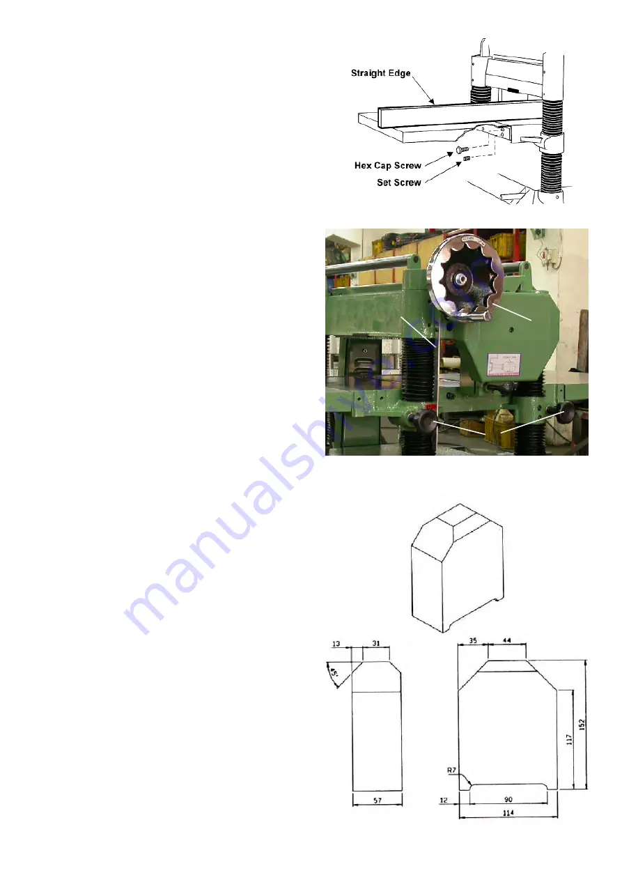
EXTENSION TABLES
1. Mount a cast iron table to the edge of the main
table with three M8 x 25 hex cap screws
(Fig. 17)
using a 12mm wrench. Do not fully tighten yet.
2. The extension table must be leveled with the
main table. Place a straight edge (such as a
jointed board) across both tables.
3. Insert three socket set screws with a 4mm hex
wrench, and screw them in or out as needed
until tables are level.
4. Securely tighten the hex cap screws.
5. Mount the second extension table to the opposite
side of the planer table, using the same
procedure.
Controlling The Depth Of Cut
The cutting depth scale is a combination inch/
metric scale (A), Fig. 18, cutting range from 0 to
8" (204mm). The distance of upward or downward
movement is controled by Handwheel (B) Fig. 18
for one evolution is 0.059" (1.5mm). Before mov-
ing table upward or downward, loosen the lock nuts
(C) as shown in Fig. 18. After choosing the proper
position, tighten the lock nuts (C),
Adjustments
Although your planer was carefully adjusted at the
factory, it should be checked before being put into
operation. Any inaccuracies due to rough handling
in transit can easily be corrected by following these
directions.
In order to check the adjustments you will need a
straight edge, feeler gage and a homemade gage
block made of hard-wood. This gage block can be
made by following the dimensions shown in Fig. 19.
Fig 19
Fig 18
Fig 18
C
B
A


