PAGE
DATE
PAGE REV
24 July 2019
B
209-00-24C
M24C PLUS FLIGHT MANUAL
104
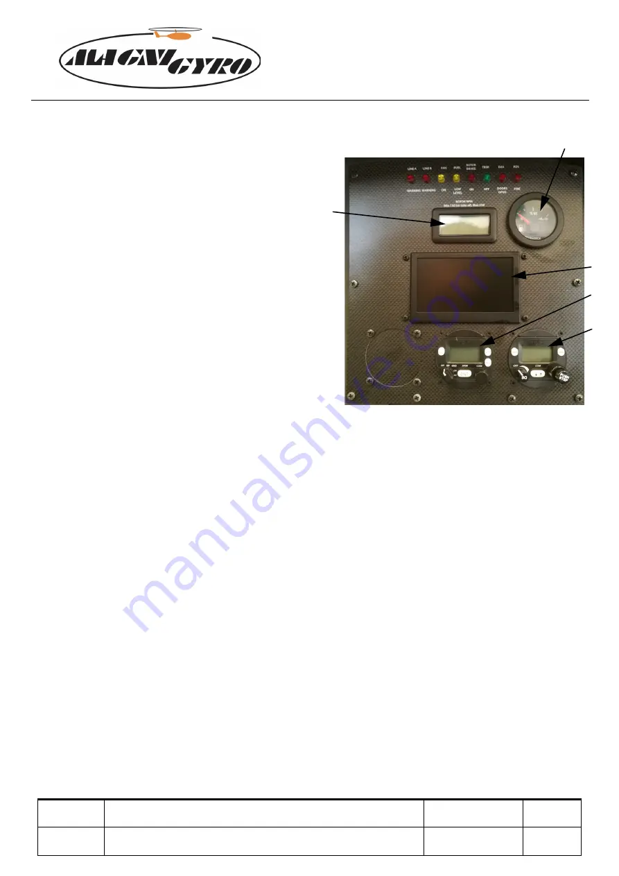
8.2.2 EMS/COMM PANEL
1. Red - LINE A: lane A voltage drop
2. Red - LINE B: lane B voltage drop
3. Yellow - FAN: cooling fan enabled
4. Yellow - RESERVE: low fuel level
5. Red - BRAKE: rotor brake (ON when engaged)
6. Green - TRIM: ON when in end position
7. Door warning system
8. Red - FIRE: fire detection system light
9. Fuel level gauge
10. Kanardia Digi engine monitor system
11. Transponder (optional)
12. Radio VHF (optional)
13. Rotor RPM: rotor rpm gauge
Figure 8.6: EMS/COMM panel
1. Red - LINE A: lane A voltage drop
This warning light indicates a voltage drop in the lane A.
2. Red - LINE B: lane B voltage drop
This warning light indicates a voltage drop in the lane B.
3. Yellow - FAN: cooling fan enabled
This light indicates that the cooling fan mounted on the radiator is running to improve the
cooling action.
4. Yellow - RESERVE: low fuel level
When this lights up it indicates that there are about 10 litres of fuel remaining, corresponding to
approximately 20 minutes of flight at maximum power. Land within 10 minutes from the
activation of this light to avoid engine shut down due to lack of fuel.
5. Red - BRAKE: rotor brake (ON when engaged)
When this light is “ON” the rotor brake lever is engaged.
6. Green - TRIM: on when in end position
When this light is “ON” the pitch trim is fully forward.
14
13
9
1 2 3 4 5 6 7 8
10
11
12
13


