Magnetrol Echotel 961 Installation And Operating Manual Download Page 4

4

SET UP AND FUNCTIONS

Set up
High – Low Level Failsafe selection:

In 

«

Hi

»

position, the process relay will de-energize (report alarm) when the transducer is

wet.

In «

Lo

» position, the process relay will de-energize (report alarm) when the transducer is 

dry.

Fault selection:

The echotel 961 is equipped with a malfunction relay separate from the 5A DPDT process relay. The separate or joined oper-

ation of both relays can be selected :   

I = in case of a malfunction, only the malfunction relay will de-energize. The process relay will only de-energize in case of a

process alarm

J = in case of a malfunction, both the malfunction relay and the process relay will de-energize

The Echotel 962 is equipped with a malfunction relay separate from the two 5A SPDT process relays. In case of a malfunction,

both the malfunction relay and the process relays will de-energize. The operation of the two process relays can be selected:

LC (level control) = the two relays operate independent and will be de-energized when the corresponding tranducer gap is

immerged/dry (following Hi/Lo setting)

PC (pump control) = the two relays operate in a latched mode, allowing to perform an automatic fill or drain pump control func-

tion in between the 2 transducer gaps. Consult below tables for proper indication and function.

Time delay setting:

Turning the potentiometer clockwise will increase the time delay from 0,5 s to 10 s. Time delay is typically used where turbu-

lence, boiling or splashing can cause false level alarms.

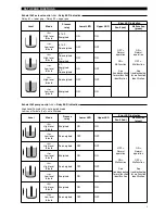
961 - Relay/ LED Indication:

When «

WET

» (wet LED): OFF = transducer gap is dry / ON = transducer gap is immerged

When «

LEVEL

» (level LED): ON = relay is energized / OFF = relay de-energized

Echotel 961: Relay/LED indication

Mode

Level

Process

relay

« LEVEL» LED

(relay - yellow)

« WET» LED

(gap - yellow)

Error LED indication

Fault (red)

Malfunction

(green)

«

Hi

»

High level

failsafe

Energized

ON

OFF

OFF =

Normal 

operation

ON =

Malfunction

See 

troubleshooting

for malfunction

identification

ON =

Normal 

operation

OFF =

Malfunction

See 

troubleshooting

for malfunction

identification

De-energized

OFF

ON

«

Lo

»

Low level

failsafe

Energized

ON

ON

De-energized

OFF

OFF

Summary of Contents for Echotel 961

Page 1: ...Ultrasonic Single and Dual Point Level Switches Installation and Operating Manual ECHOTEL 961 962 LINE POWERED Model 961 Model 962...

Page 2: ...when ordering parts MOUNTING Nameplate part number serial n Varivent These units are in compliance with 1 The EMC directive 2014 30 EU The units have been tested to EN 61326 1997 A1 A2 2 Directive 20...

Page 3: ...I Lo J Malfunction SPDT relay Malfunction relay Process relay s 100 to 265 V AC 12 to 35 V DC NC C NO NC C NO NC C NO Process relay s Input power 1 x DPDT 961 2 x SPDT 962 relay s Ground HAZARDOUS ARE...

Page 4: ...e independent and will be de energized when the corresponding tranducer gap is immerged dry following Hi Lo setting PC pump control the two relays operate in a latched mode allowing to perform an auto...

Page 5: ...o Low level failsafe Energized ON ON Relay 1 lower gap Relay 2 upper gap Echotel 962 pump control PC Relay LED indication Level Mode Process relay Lower LED Upper LED Error LED indication Fault red Ma...

Page 6: ...ring input power Check for malfunction 962 See below No change in output between wet gap dry gap Gap may be plugged by solids dense foam Clean the transducer Gap is out of reach of liquid Check mounti...

Page 7: ...Cast stainless steel cover digit 10 2 or 3 Blind Deep drawn stainless steel cover digit 10 4 or 5 Blind With window 004 9192 009 036 4410 010 004 9224 014 032 3934 001 036 5702 002 2 O Ring digit 10 0...

Page 8: ...th M20 x 1 5 cable entry 2 entries one plugged 2 Cast stainless steel with 3 4 NPT cable entry 2 entries one plugged 5 Deep drawn 304 stainless steel with M20 x 1 5 cable entry 2 entries one plugged 4...

Page 9: ...lastic transducers 3 T 1 1 2 Tri clamp 4 T 2 Tri clamp V V DN 65 Varivent type N Hygienic B S DN 25 DIN 11851 C S DN 40 DIN 11851 D S DN 50 DIN 11851 CPVC anges for CPVC transducers Kynar cladded SST...

Page 10: ...connection 102 4 6 0 25 46 1 8 Typical 22 9 0 90 Actuation length A for NPT connection Actuation length B for NPT connection Actuation length A for BSP connection Actuation length B for BSP connection...

Page 11: ...hes Cable entry 60 2 36 125 4 92 43 52 2 05 58 2 28 109 4 28 43 View 29 1 14 22 9 0 90 Actuation Length Tri Clamp 35 1 38 22 9 0 90 Actuation Length DIN 11851 46 1 81 22 9 0 90 6 0 25 6 0 25 6 0 25 Ac...

Page 12: ...s SA1 shock ANSI ISA S71 03 Class VC2 vibration Net weight Aluminium Deep drawn 304 SST 1 kg 2 2 lbs electronics only Cast SST 2 5 kg 5 5 lbs electronics only Description Specification Response time 0...

Page 13: ...s pressure bar 30 25 20 15 10 5 40 0 40 80 120 0 Kynar Transducer Ratings Process temperature C Process pressure bar 30 25 20 15 10 5 40 0 40 80 120 0 CPVC Transducer Ratings Metal Transducer Ratings...

Page 14: ...14 Notes...

Page 15: ...15 Notes...

Page 16: ...y contacting the factory Please supply the following information 1 Purchaser Name 2 Description of Material 3 Serial Number and Ref Number 4 Desired Action 5 Reason for Return 6 Process details Any un...

Reviews: