Magnetrol C29 Installation And Operating Manual Download Page 14

14

46-605 Flanged External Cage Float Actuated Liquid Level Switches

screw at point of contact between screw and lever.Such
wear can cause false switch actuating levels. See switch
mechanism bulletin supplied with control should switch
adjustment or replacement become necessary.

2. DO NOT operate your control with defective or malad-

justed switch mechanisms. Refer to bulletin on switch
mechanisms furnished for service instructions. See

Switch

and Housing Reference, Section 6.2.2.

3. Level controls may sometimes be exposed to excessive heat

or moisture. Under such conditions, insulation on electrical
wiring may become brittle, eventually breaking or pealing
away. The resulting “bare” wires can cause short circuits.

NOTE: Check  wiring  carefully  and  replace  at  the  first  sign  of  brittle

insulation.

4. Vibration may cause terminal screws to loosen. Check all

terminal connections to be  certain that screws are tight.

5. On units with pneumatic switches, air (or gas) lines sub-

jected to vibration may eventually crack or become loose
at connections causing leakage. Check lines and connec-
tions carefully and repair or replace if necessary.

NOTE: As a matter of good practice, spare switches should be kept

on hand at all times.

4.1.3 Inspect entire unit periodically

Isolate control from vessel. Raise and lower liquid level to
check for switch contact and reset.
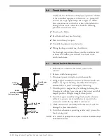
4.2

What To Avoid

1. Never leave switch housing cover off the control longer

than necessary to make routine inspections.

2. Never place a jumper wire across terminals to “cut-out”the

control. If a “jumper” is necessary for test purposes, be cer-
tain it is removed before placing  control into service.

3. Never attempt to make adjustments or replace switches

without reading instructions carefully. Certain adjustments
provided for in level controls should not be attempted in
the field. When in doubt, consult the factory or your local
representative.

4. Never use lubricants on pivots of switch mechanisms.

A sufficient amount of lubricant has been applied at the
factory to ensure a lifetime of service. Further  oiling is
unnecessary and will only tend to attract dust and dirt
which can interfere with mechanism operation.

Summary of Contents for C29

Page 1: ...Float Actuated Liquid Level Switches Flanged External Cage Installation and Operating Manual...

Page 2: ...used in a manner not specified by manufacturer protection provided by equipment may be impaired Notice of Copyright and Limitations Magne tr ol Magne tr ol logotype and are registered trademarks of M...

Page 3: ...4 1 Recommended Practice 13 4 1 1 Keep control clean 13 4 1 2 Inspect switch mechanisms terminals and connections monthly 13 4 1 3 Inspect entire unit periodically 14 4 2 What To Avoid 14 5 0 Specific...

Page 4: ...level alarm for maximum protection 1 3 Piping An instruction tag secured to the control gives dimensional data on switch actuating levels referenced from center line of upper side tank connection Posi...

Page 5: ...e units are shipped from the factory with the enclosing tube tightened and the switch housing set screw locked to the enclosing tube Failure to loosen the set screw prior to repositioning the supply a...

Page 6: ...housing cover NOTE It is the responsibility of the customer to comply with applica ble installation codes and practices Class I Division 1 locations may contain explosive gas mixtures Appropriate pre...

Page 7: ...ing or breaking an electrical circuit Refer to Figure 4 As the liquid level falls the float drops and moves the attraction sleeve out of the magnetic field releasing the switch mechanism magnet The te...

Page 8: ...NOTE To widen the differential by one inch the lower jam nuts must be set proportionately lower on the stem i e in this example by 1 inch 2 Make sure power source is turned off 3 Unscrew and remove s...

Page 9: ...he base of the switch housing Rotate switch housing to correct position and tighten set screws Refer to Figure 1 on page 5 Caution After increasing gap setting be certain to check for proper operation...

Page 10: ...A and readjust new assembly to the previously determined level differential settings See Switch Differential Adjustment Section 2 4 5 Replace new float and stem assembly into head flange and install n...

Page 11: ...r to the control 2 Remove switch housing cover 3 Disconnect power wiring from switch assembly 4 Swing magnet assembly in and out by hand to check care fully for any sign of binding Assembly should req...

Page 12: ...dium line connections to switch housing 5 Perform system shutdown to relieve pressure from float chamber of control Allow unit to cool 6 Close shutoff valves if equipped to isolate control from vessel...

Page 13: ...reventive Maintenance Periodic inspections are necessary to keep your level control in good working order This control is a safety device to protect the valuable equipment it serves A systematic progr...

Page 14: ...ation may eventually crack or become loose at connections causing leakage Check lines and connec tions carefully and repair or replace if necessary NOTE As a matter of good practice spare switches sho...

Page 15: ...listed as TYPE 4X 7 9 Class I Div 1 Group B Class II Div 1 Groups E F G ATEX IEC Ex All with an electric switch mechanism and an ATEX II 2 G EEx d IIC T6 ATEX housing 94 9 EC IEC Ex Ex d IIC T6 IP 66...

Page 16: ...2 Flanged Side Side Actuating Levels A B C A B C A B C HL LL A B C A B C A B C HL LL C29 76 9 75 3 44 14 38 13 81 6 87 18 38 14 46 6 87 19 06 2 02 2 92 247 87 365 350 174 466 367 174 484 51 74 D30 65...

Page 17: ...78 96 8 46 215 Side Side Flanged Conduit Connections D Electrical Switches TYPE 4X 7 9 1 NPT Group B 1 NPT Pneumatic Switches TYPE 1 1 4 NPT NOTES 1 Switch actuating levels HL LL are given for minimu...

Page 18: ...ete control less float chamber 10 bolts 7 and nuts 8 089 6567 003 Series Type Bulletin Dry contact B C D 42 683 Hermetically sealed F 42 683 Hermetically sealed HS 42 694 Bleed type pneumatic J 42 685...

Page 19: ...osing tube kit includes items 4 and 5 089 5933 004 089 5933 011 Enclosing tube gasket 012 1204 001 012 1301 002 Head flange kit includes items 5 6 7 8 and 9 089 4206 001 089 4206 002 Flange gasket 012...

Page 20: ...Model and serial number of control B Replacement assembly kit part number 19 18 20 11 10 9 4 2 14 3 12 5 8 7 6 13 1 15 17 16 6 2 Tandem Flanged External Cage Models 1 Housing cover 2 Housing base 3 Sw...

Page 21: ...des items 9 10 11 12 13 14 and 15 Lower float and stem kit Special order includes items 9 16 17 18 and 19 Float chamber kit Special order includes items 7 8 9 and 20 D30 TDM J30 TDM L30 TDM 6 2 5 Mode...

Page 22: ...TION TYPE AND SIZE PNEUMATIC SWITCH MECHANISM AND ENCLOSURE Connection flanges are ASME B16 5 raised face Electric switch mechanism and enclosure codes on next page Models are limited to maximum tempe...

Page 23: ...G9 Series HS Hermetically Sealed 5 amp Snap Switch with Wiring Leads 50 to 550 46 to 288 SPDT 1 HMJ HMK HMJ HMK 2 HMN HMP HMN HMP DPDT 1 HMS HMT HMS HMT 2 HMY HMZ HMY HMZ Series HS Hermetically Sealed...

Page 24: ...turned If this is desired notify the factory of both the model and serial numbers of the control to be replaced In such cases credit for the materials returned will be determined on the basis of the a...

Reviews: