background image


Flex 8RS System Instruction Manual 

December 2012 

26 of 36 

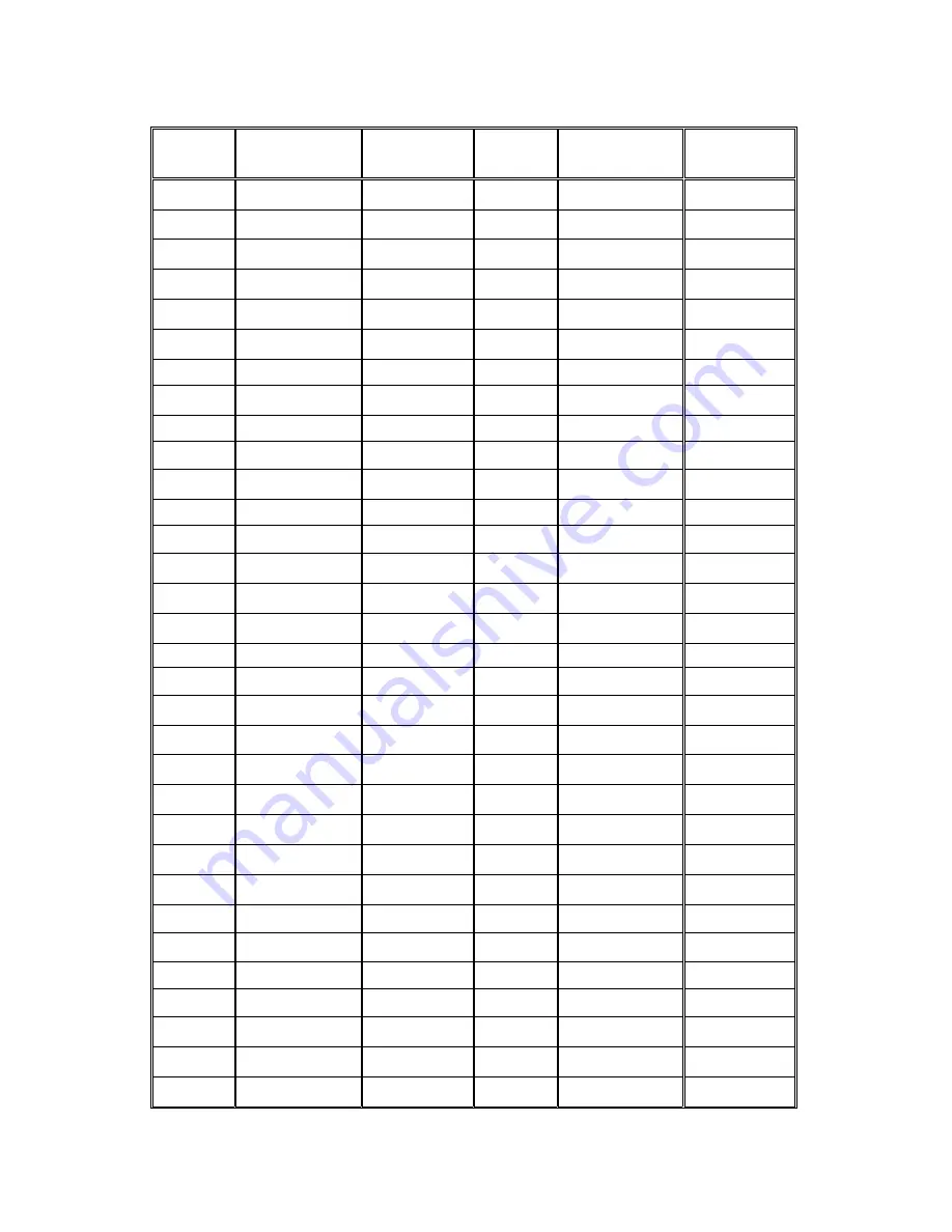
5. SYSTEM CHANNELS TABLE 

Channel  

Frequency 

Dip-switch 

Setting 

Channel 

Frequency 

Dip-switch 

Setting 

01 

433.000MHZ 000000 

32 

433.775MHZ 100000 

01 

433.000MHZ 000001 

33 

433.800MHZ 100001 

02 

433.025MHZ 000010 

34 

433.825MHZ 100010 

03 

433.050MHZ 000011 

35 

433.850MHZ 100011 

04 

433.075MHZ 000100 

36 

433.875MHZ 100100 

05 

433.100MHZ 000101 

37 

433.900MHZ 100101 

06 

433.125MHZ 000110 

38 

433.925MHZ 100110 

07 

433.150MHZ 000111 

39 

433.950MHZ 100111 

08 

433.175MHZ 001000 

40 

433.975MHZ 101000 

09 

433.200MHZ 001001 

41 

434.000MHZ 101001 

10 

433.225MHZ 001010 

42 

434.025MHZ 101010 

11 

433.250MHZ 001011 

43 

434.050MHZ 101011 

12 

433.275MHZ 001100 

44 

434.075MHZ 101100 

13 

433.300MHZ 001101 

45 

434.100MHZ 101101 

14 

433.325MHZ 001110 

46 

434.125MHZ 101110 

15 

433.350MHZ 001111 

47 

434.150MHZ 101111 

16 

433.375MHZ 010000 

48 

434.175MHZ 110000 

17 

433.400MHZ 010001 

49 

434.200MHZ 110001 

18 

433.425MHZ 010010 

50 

434.225MHZ 110010 

19 

433.450MHZ 010011 

51 

434.250MHZ 110011 

20 

433.475MHZ 010100 

52 

434.275MHZ 110100 

21 

433.500MHZ 010101 

53 

434.300MHZ 110101 

22 

433.525MHZ 010110 

54 

434.325MHZ 110110 

23 

433.550MHZ 010111 

55 

434.350MHZ 110111 

24 

433.575MHZ 011000 

56 

434.375MHZ 111000 

25 

433.600MHZ 011001 

57 

434.400MHZ 111001 

26 

433.625MHZ 011010 

58 

434.425MHZ 111010 

27 

433.650MHZ 011011 

59 

434.450MHZ 111011 

28 

433.675MHZ 011100 

60 

434.475MHZ 111100 

29 

433.700MHZ 011101 

61 

434.500MHZ 111101 

30 

433.725MHZ 011110 

62 

434.525MHZ 111110 

31 

433.750MHZ 011111 

I-CHIP


111111* 


*  When set to all “1” the priority goes to the channel assigned inside the I-CHIP.


Summary of Contents for Flex 12RS System

Page 1: ...Flex 8RS System Radio Control Equipment Instruction Manual 0 FLEX 8RS ME R1 December 2012 Copyright 2012 Magnetek Material Handling...

Page 2: ...1 800 288 8178 Website www magnetekmh com e mail info magnetekmh com Fax Numbers Main 1 800 298 3503 Sales 1 262 783 3510 Service 1 262 783 3508 Magnetek Inc has additional satellite locations for Can...

Page 3: ...ystem is used Plant safety rules and procedures of the employers and the owners of facilities where the Magnetek Products are being used Regulations issued by the Occupational Health and Safety Admini...

Page 4: ...s 13 4 1 2 Push Button Functions Setup 14 4 1 3 Channel Change via Push Buttons 17 4 1 4 Optional 4 Digit Security Code 18 4 1 5 I CHIP 19 4 2 RECEIVER UNIT 20 4 2 1 System Channel Settings 20 4 2 2 R...

Page 5: ...er channels Over one million unique ID codes 20bit Each and every Flex system has its own unique ID codes and serial number no repeats Advanced controls The Flex system utilizes advanced microprocesso...

Page 6: ...ing or maintenance procedure practice etc which if not strictly observed could result in damage to or destruction of equipment or loss of functional effectiveness Cautions are highlighted as shown bel...

Page 7: ...F THIS PRODUCT ARE NOT DESIGNED TO INTERFACE DIRECTLY TO TWO STATE SAFETY CRITICAL MAINTAINED FUNCTIONS I E MAGNETS VACUUM LIFTS PUMPS EMERGENCY EQUIPMENT ETC A MECHANICALLY LOCKING INTERMEDIATE RELAY...

Page 8: ...r and other people clear of lifted loads and to avoid pinch points continuously watch and monitor status of lifted loads know and follow cable and hook inspection procedures know and follow the local...

Page 9: ...provided for the transmitter unit and the transmitter unit should always be placed there when not in use This precaution will help prevent unauthorized people from operating the material handling equi...

Page 10: ...than 24 hours at a time Do not charge batteries in a hazardous environment Do not short the charger Do not attempt to charge a damaged battery Use only Magnetek Telemotive approved chargers for the ap...

Page 11: ...N 3 1 RS System Description 8 RS Types TYPE B A B Receiver Select with Bridge Receiver 8 Button Transmitter bottom two buttons for A B Select 3 Receivers A B and Bridge TYPE C A B C D Receiver Select...

Page 12: ...shown for reference Fig 01 Fig 02 1 Emergency Stop Button 9 Push Button 5 2 Removable Power Key Switch 10 Push Button 7 3 Push Button 2 11 Strap Ring 4 Push Button 4 12 System Information 5 Push Butto...

Page 13: ...ber 2012 10 of 36 3 2 2 Internal Illustration Fig 03 Fig 04 1 Encoder Board 6 I CHIP 2 Aerial Antenna 7 Function Dip Switch 3 Transmitting Module 8 Channel Dip Switch 4 Status LED Display 9 Battery Co...

Page 14: ...ual December 2012 11 of 36 7 6 1 2 3 4 5 3 3 RECEIVER UNIT 3 3 1 External Illustration Fig 05 1 External Antenna Jack 5 COM LED Display 2 Power LED Display 6 Output Contact Diagram 3 Status LED Displa...

Page 15: ...tion Manual December 2012 12 of 36 I CHIP PORT 1 2 3 4 JP7 JP6 JP5 JP4 JP3 JP2 JP1 SYSTEM FUNCTIONS TEST 3 3 2 Internal Illustration Fig 06 1 Receiving Module 3 AC Line Filter Board 2 Decoder Relay Bo...

Page 16: ...re used for channel programming refer to Fig 08 below The system channels table located on page 26 illustrates which dip switch setting corresponds to which channel Once the transmitter channel is alt...

Page 17: ...he system in interlock and non interlock modes When interlock mode is selected dipswitch 7 is on up only 1 receiver can be selected at a time When non interlock mode is selected dipswitch 7 is off dow...

Page 18: ...1 interlock Down 0 non interlock Receiver A Receiver B S N XXXXXX TYPE 01 S N XXXXXX TYPE 02 Receiver C Receiver D S N XXXXXX TYPE 04 S N XXXXXX TYPE 08 When receiver is selected relays respond to TX...

Page 19: ...Button 6 1st speed Relay K3 Button 5 2nd speed Relay K4 Button 6 2nd speed Relay K5 Bridge 1 Indicator relay maintained closed when Bridge 1 is selected to be active Relay K6 Bridge 2 Indicator relay...

Page 20: ...06 b Select a new channel by pressing PB1 and PB2 on the transmitter Press PB1 to increment the units 1 and PB2 to increment the tens 10 Examples Press PB2 two times and then PB1 four times will give...

Page 21: ...s time fast orange blinks are displayed on the Status LED telling you to reconfirm the 4 digit security code you have just entered A green light will appear once you have re entered the same 4 digit s...

Page 22: ...igurations stored inside the I CHIP will be erased and be replaced by the new settings For safety purposes the system serial number ID code stored inside the I CHIP cannot be changed directly on the t...

Page 23: ...on the receiver module refer to Fig 12 above only the first six 6 positions are used for channel programming refer to Fig 13 below The system channels table located on page 26 illustrates which dip sw...

Page 24: ...Dip switch 1 Scanning all 62 channels manufacture preset For standard operation 2 Single fixed channel Auto scanning function disabled 3 Scanning 2 channels only 4 Scanning 3 channels only If the fir...

Page 25: ...rate 2nd speed relay NOTE All settings are pre set at the factory information to be used for replacement receivers only Each dip switch dip position 1 8 on the decoder relay board corresponds to four...

Page 26: ...ff or emergency stop command is initiated JP1 Inserted JP2 Blank Receiver MAIN opens after 5 minutes of system inactivity JP1 Blank JP2 Inserted Receiver MAIN opens after 30 minutes of system inactivi...

Page 27: ...tter Settings Function Dip Switch 1 2 3 4 5 6 7 8 T H Interlocked Off On Off Off Off Off On Off T H Non Interlocked Off On Off Off Off Off Off Off Flex RS System Type C A B C D Trolley Hoist Receiver...

Page 28: ...ansfer system information from the I CHIP to the receiver then you must first insert JP6 jumper prior to inserting the I CHIP then wait for the green light to appear on the Status LED At this time the...

Page 29: ...34 075MHZ 101100 13 433 300MHZ 001101 45 434 100MHZ 101101 14 433 325MHZ 001110 46 434 125MHZ 101110 15 433 350MHZ 001111 47 434 150MHZ 101111 16 433 375MHZ 010000 48 434 175MHZ 110000 17 433 400MHZ 0...

Page 30: ...6 1 OUTPUT RELAY CONTACT DIAGRAM For 12 24VDC power supply wire 1 corresponds to the negative charge and wire 3 corresponds to the positive charge Wire 2 is for GROUND Wire 6 is for Normal Close and w...

Page 31: ...nstallation 4 Make sure the power source to the receiver is set correctly 5 Switch off the main power source to the crane or equipment prior to installation 6 3 STEP BY STEP INSTALLATION Fig 18 1 For...

Page 32: ...or system wiring please refer to page 27 6 4 SYSTEM TESTING 1 Turn on the power source to the receiver and test the MAIN relay output by pressing the red emergency stop button and observe that it prop...

Page 33: ...he transmitter handset for any sign of system irregularities refer to Status Light Indicators Warnings on page 33 If the system is normal the Status LED will light up green for two 2 seconds d If ther...

Page 34: ...rotate the power key to Start position to resume operation depends on JP3 setting on page 23 g After 5 minutes of inactivity push button not pressed the receiver MAIN will be disconnected temporarily...

Page 35: ...ning mode prior to changing the transmitter channel you must first deactivate the receiver MAIN by shutting off the transmitter power or press down the emergency stop button Please refer to page 21 if...

Page 36: ...a defective push button condition occurs 2 red blinks type 3 above find out which push button is defective by pressing all the push buttons on the transmitter one at a time If the push button is in g...

Page 37: ...mitter serial number ID code 6 Constant red Receiver under voltage LV output relay activated 7 No light displayed Decoding microprocessor is defective 7 2 3 Receiver SQ Light Indication Type Display T...

Page 38: ...tartup procedure is initiated within 100 meters 300 feet from the receiver location No response when transmitter push button is pressed Damaged hardware Defective transmitting and receiving module Che...

Page 39: ...ity 116dBm Spurious Emission 50dB Antenna Impedance 50 ohms Responding Time 60 Milliseconds average Transmitting Power 1 0mW Enclosure Type NEMA 4X Enclosure Rating IP 66 Output Contact Rating 250V 8...

Reviews: