


1-10-2
E9E8AFIS
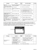
< DVD Section >
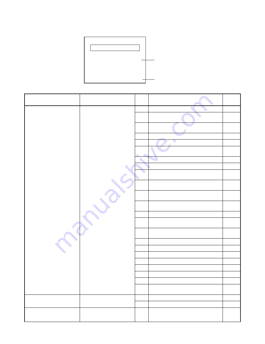
Note: If an error occurs, a message with the error number appears on the screen.
Message
Solution
Error
No.
Error Description
Priority
Can not record on this disc.
Insert the recordable disc, and
ensure the disc status satisfies
the recording requirements.
1
An error occurs during data reading.
-
2
There is no reply for 15 seconds in Test
Unit Ready.
-
3
Cannot write the data after trying three
times.
-
4
An error occurs with OPC.
-
5
During recovery in a record.
-
6
An error occurs even if recovery has been
tried three times.
-
7
An error occurs in a format.
-
8
It cannot start an encode.
-
9
NV_PCK/RDI_PCK is not in encoded
data.
-
10
Encode Pause condition continued for 10
minutes.
-
11
Encode Pause condition continued in
normal REC condition for 10 minutes.
-
12
Difference in the address and can not get
StreamID of RDI/VIDEO.
-
13
It is a reply that “ATAPI is not readable.”
-
14
Cannot write the data after recovering
SMALL VMGI.
-
15
Cannot write the data after DVD-R
Reverse Track.
-
16
An error occurs in Finalize Close.
-
17
An error occurs in Rec Stop Close.
-
18
An error occurs in PCA Full (DVD_R).
-
19
Safety Stop occurs during editing.
-
20
High Speed Disc.
2
21
The disc is not formatted.
5
22
Disc Error has occurred.
3
24
The disc except DVD-R/RW or finalized
DVD-R.
1
This program is not allowed to
be recorded.
You cannot record copy
prohibited programs.
25
During the Macrovision picture input.
11
26
During the CGMS picture input.
12
This disc is protected and not
recordable.
Release the disc protect
setting in the Disc Setting
menu.
29
Disc Protected Disc.
7
Recording Error
You cannot record on this disc as
Power Calibration Area is full.
E35
Error No.
Error message
Summary of Contents for ZV420MW8 - DVDr/ VCR Combo
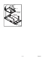
Page 19: ...1 6 6 E9E8ADC Fig D10 19 Deck Pedestal 20 Front Bracket R S 18 S 18 S 18 S 18 S 19 ...
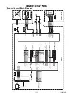
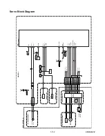
Page 39: ...1 12 3 Main 1 7 Schematic Diagram E9E8ASCM1 ...
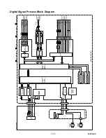
Page 41: ...1 12 5 Main 3 7 Schematic Diagram E9E8ASCM3 ...
Page 42: ...1 12 6 Main 4 7 Schematic Diagram E9E8ASCM4 ...
Page 43: ...1 12 7 Main 5 7 Schematic Diagram E9E8ASCM5 ...
Page 44: ...1 12 8 Main 6 7 Schematic Diagram E9E8ASCM6 ...
Page 45: ...1 12 9 Main 7 7 Schematic Diagram E9E8ASCM7 ...
Page 47: ...1 12 11 Front Jack Schematic Diagram E9E8ASCFJ ...
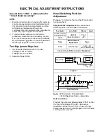
Page 63: ...1 15 3 R4NTI Push close 0 08 V 0 02 s Push Close detection Threshold level ...


