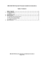
1-5-1
E7C50DC
CABINET DISASSEMBLY INSTRUCTIONS
1. Disassembly Flowchart
This flowchart indicates the disassembly steps to gain
access to item(s) to be serviced. When reassembling,
follow the steps in reverse order. Bend, route, and
dress the cables as they were originally.
2. Disassembly Method
Note:
(1) Identification (location) No. of parts in the figures
(2) Name of the part
(3) Figure Number for reference
(4) Identification of parts to be removed, unhooked,
unlocked, released, unplugged, unclamped, or
desoldered.
P = Spring, L = Locking Tab, S = Screw,
CN = Connector
* = Unhook, Unlock, Release, Unplug, or Desolder
e.g. 2(S-2) = two Screws (S-2),
2(L-2) = two Locking Tabs (L-2)
(5) Refer to “Reference Notes.”
Reference Notes
1.
CAUTION 1:
Locking Tabs (L-1) and (L-2) are
fragile. Be careful not to break them.
ID/
Loc.
No.
Part
Removal
Fig.
No.
Remove/*Unhook/
Unlock/Release/
Unplug/Desolder
Note
[1]
Top Cover
D1 6(S-1)
---
[2]
Front
Assembly
D2
*5(L-1), *CN1061,
*3(L-2), Shield A
1
[3]
SW CBA
D2 *2(L-3)
---
[4]
DVD
Mechanism
& DVD Main
CBA
Assembly
D3
4(S-3a), (S-3b),
*CN101, *CN701,
Locking Card Spacers,
M-PCB Plate Earth
---
[5]
Power
Supply
CBA
D4 4(S-4), *CN1060
---
[6]
Rear Panel
D5 6(S-5), (S-6), (S-7)
---
[7]
AV CBA
D5
5(S-8), Heat Sink
Plate
---
[8]
Front
Bracket
D5 (S-9)
---
↓
(1)
↓
(2)
↓
(3)
↓
(4)
↓
(5)
[3] SW CBA
[2] Front Assembly
[1] Top Cover
[5] Power Supply CBA
[6] Rear Panel
[8] Front Bracket
[4] DVD Mechanism &
DVD Main CBA Assembly
[7] AV CBA
[1] Top Cover
(S-1)
(S-1)
(S-1)
Fig. D1
Summary of Contents for ZC352MW8
Page 1: ...SERVICE MANUAL DVD RECORDER ZC352MW8...
Page 27: ...1 10 4 AV 2 4 Schematic Diagram E7C50SCAV2...
Page 28: ...1 10 5 E7C50SCAV3 AV 3 4 Schematic Diagram...
Page 29: ...1 10 6 E7C50SCAV4 AV 4 4 Schematic Diagram...
Page 31: ...1 10 8 SW Schematic Diagram E7C50SCSW...
Page 37: ...1 10 14 DTV Module 1 2 Schematic Diagram E7C50SCDTV1...
Page 38: ...1 10 15 DTV Module 2 2 Schematic Diagram E7C50SCDTV2...
Page 39: ...1 10 16 AV CBA Top View BE7C50F01011A...
Page 43: ...1 10 20 BE7C50F01011C SW CBA Top View SW CBA Bottom View...