background image

10

PREPARATION

No supplied cables are used with these connections:


• Please purchase the necessary cables at your local store.

Before you connect:

Be sure your antenna or other device is connected properly 
before plugging in the AC power cord.
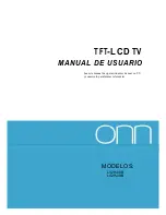
Antenna Connection

Connect the RF coaxial cable on your home outlet to the 
antenna input jack of this unit.

VHF / UHF analog   

VHF / UHF  analog   

or 

or 

DTV antenna

DTV antenna

cable TV signal

cable TV signal

or

RF coaxial cable

RF coaxial cable


Once connections are completed, turn on the unit and begin 
initial setup. Channel scanning is necessary for the unit to 
memorize all available channels in your area. 

[Initial Setup]


p. 11

Note


• If you have any question about the DTV’s antenna, visit

www.antennaweb.org for further information.


•  Depending on your antenna system, you may need different types 

of combiners (mixers) or separators (splitters) for HD TV signal 

the minimum RF bandpass on these devices is 2,000MHz or 2GHz.


•  For your safety and to avoid damage to this unit, please unplug the 

RF coaxial cable from the antenna input jack before moving the 

unit.


•  If you did use an antenna to receive analog TV, it should also 

work for DTV reception. Outdoor or attic antennas will be more 

effective than a set top or inside antenna.


•  To switch your reception source easily between antenna and cable, 

install an antenna selector.


•  If you are not receiving a signal from your cable service, contact the 

Cable provider.

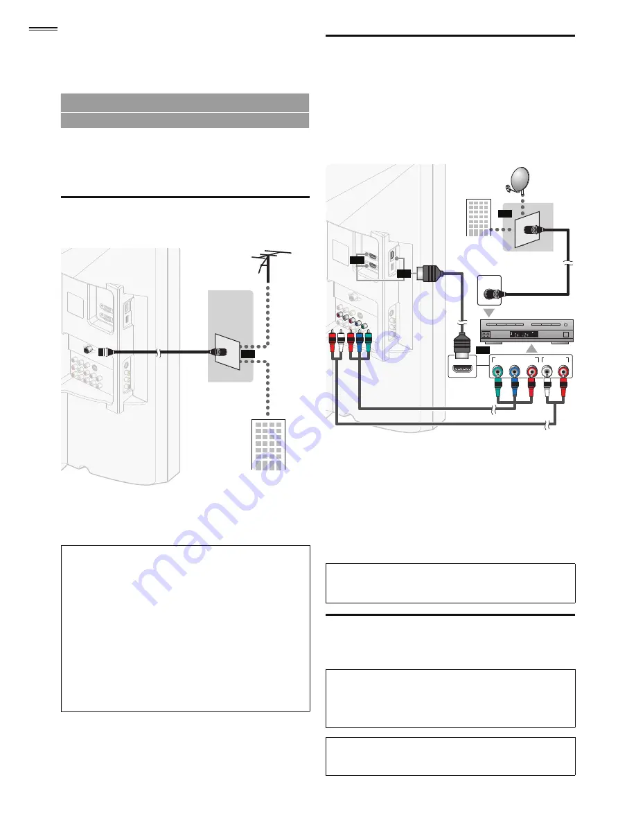
Connection to Cable Receiver or 

Satellite Box

Use an HDMI or Component Video cables to connect the 
HDMI or the Component Video Input jacks of the unit to the 
HDMI or the Component Video output jacks of the cable 
receiver / satellite  box.
If you connect to the unit’s Component Video Input jacks, 
connect Analog Audio cables to the Analog Audio L/R Input 
jacks right  beside the Component Video connector jacks.


STEREO
PCM

ANT IN

COMPONENT VIDEO OUT

Pr/Cr

Pb/Cb

Y

AUDIO OUT

R

L

HDMI OUT

(red)

(red)

(blue)

(blue)

(green)

(green)

cable receiver /

cable receiver /

satellite box

satellite box

cable TV signal 

cable TV  signal 

including PPV

including PPV

component video cables 

component video cables 

(red / blue / green) and audio cables

(red / blue / green)  and  audio  cables

RF coaxial cable

RF coaxial cable

or

or

or

HDMI cable

HDMI cable

satellite dish

satellite dish

or


 You can also connect this unit to the cable receiver or satellite 
box other than the HDMI or the Component Video output jacks 
or Composite Video output jack (


p.   26

) because they might 

have different output jacks.
Required cables and connecting methods of the cable receiver / 
satellite box, or the availability channel for the clear QAM may 
differ depending on the cable / satellite provider or local TV 
broadcaster.
For more information, please contact your cable / satellite provider 
or local TV broadcaster.

Note


• Use an HDMI cable with the HDMI logo (a certi

fi

 ed HDMI cable).

High Speed HDMI cable is recommended for the better compatibility.

Plug In the AC Power Cord

Make sure that the AC power cord must be plugged to an AC 
outlet after all the necessary connections are made.

Caution:


•  Do not connect the AC power cord to a power supply outside 

the indicated voltage of this unit (AC 120V).

Connecting the AC power cord to a power supply outside of this 

range may result in 

fi

 re or electrical shocks.

Note


•  Each time you plug in the AC power cord, no operations will be 

performed for a few seconds. This is not a malfunction.

Summary of Contents for 40MF401B

Page 1: ...pide Incluse Gu a de Uso R pido Incluida MODEL NUMBER SERIAL NUMBER 1 866 341 3738 1 866 341 3738 1 866 341 3738 Necesita ayuda inmediata Owner s Manual Manuel du Propri taire Manual del Propietario E...

Page 2: ...ou ll receive all of the privileges to which you re entitled including special money saving offers Return your Product Registration Card or register online at www magnavox com support today to get the...

Page 3: ...levisions must comply with recommended international global safety standards for tilt and stability properties of its cabinet design Do not compromise these design standards by applying excessive pull...

Page 4: ...more around this apparatus WARNING To prevent injury this apparatus must be securely attached to the wall in accordance with the instructions Do not place the unit on the furniture that is capable of...

Page 5: ...5 English Child Safety SYL Eme_Child Safety_1EMN24522_v1 1 2008 12 17 18 05 53...

Page 6: ...Symbols Used in this Manual 7 Attaching the Base 7 Mounting the Unit onYour Furniture 7 Remote Control Function 8 Installing the Batteries 8 Control Panel 9 Terminals 9 PREPARATION Antenna Connection...

Page 7: ...e steps 1 Check the text FRONT with arrow on the Base s bottom to ensure it is being installed in the correct direction Spread a thick and soft cloth over a table as shown at step 2 Place the main uni...

Page 8: ...12 4 FREEZE p 12 Press to freeze screen image 5 OK p 11 6 cursor p 11 7 BACK p 14 8 VOL p 13 9 PREV CH p 12 Press to return to previously viewed channel 10 SLEEP p 12 11 FORMAT p 13 Press to select a...

Page 9: ...ack the picture JPEG and video Motion JPEG files stored on a USB storage device or when software update is needed 11 S Video Composite Video Audio L R Input jacks for VIDEO 2 p 26 Rear Panel 12 Cable...

Page 10: ...HDMI or the ComponentVideo output jacks of the cable receiver satellite box If you connect to the unit s ComponentVideo Input jacks connect Analog Audio cables to the Analog Audio L R Input jacks righ...

Page 11: ...energy efficiency for home setting and it can be adjusted through a choice of picture and sound quality according to your preference Use this setting to remove the E Sticker if visible from the displa...

Page 12: ...PC Input Video2 Video1 Component Pressing CH reverses the direction of the input modes Freeze Mode can freeze the image shown on theTV screen for 5 minutes Press FREEZE to freeze the image Freeze The...

Page 13: ...top of the picture Zoom displays a 4 3 picture at a 16 9 size at its maximum size that is more vertically stretched to fill the screen This crops out the top and bottom of the picture Wide displays th...

Page 14: ...put jack TV PG DLSV 480i 480i SD SD CC CC Video1 The information display will automatically disappear in 1 minute ECO You can turn on ECO Mode to conserve power Press ECO once to turn on ECO Mode and...

Page 15: ...es Language USB Picture Page 16 Adjusting the picture mode or customize the picture quality as your preference Sound Page 16 Adjusting the sound mode equalizer and some other sound functions Setup Pag...

Page 16: ...the desired option then press OK On Reduces noise in an image Off Sets noise reduction to off Note This function is disabled when PC input is selected Setting will be in gray Sound Before you begin Yo...

Page 17: ...m Channel List Add Channels Antenna 2 Adjust the following items Autoprogram If you switch wires e g between antenna and CATV or if you move the unit to a different area after the initial setting or i...

Page 18: ...he Number buttons to enter the number of the channel you want to add then press OK Picture Sound Setup Features Language USB For analog channels select a channel to be added using number keys For digi...

Page 19: ...e Use this menu to change the settings for digital caption service 1 Use to select Digital Caption Service then press OK 2 Use to select the desired digital caption service then press OK Off Select if...

Page 20: ...ed Caption Child Lock ECO fun Link HDMI CEC Location E Sticker Current Software Info On Home 2 Use the Number buttons to enter the 4 digit numbers for your PIN code Features Language _ Enter PIN When...

Page 21: ...sired rating then press OK repeatedly to switch between View and Block Picture Sound Setup Features Language USB FV V S L D TV MA TV 14 TV PG TV G TV Y7 TV Y Select OK View Block BACK Back Sub Rating...

Page 22: ...Disables all fun Link Auto Device Off You can set your device to turn off by interlocking from this unit s power Use to select the desired setting then press OK On Your connected fun Link device turn...

Page 23: ...e below 1 Use to select E Sticker then press OK 2 Use to select Off then press OK Off You can turn off E Sticker Top E Sticker is displayed on top of theTV screen Bottom E Sticker is displayed on bott...

Page 24: ...Detail More Detail Press 1 to display file details below Name Album Date Size and Next Press 1 again to remove file details Start show Press 4 or OK to start the slide show While the slide show is on...

Page 25: ...the file is not supported an error message appears When the USB storage device is not recognized try reconnecting it again Motion JPEG file with an extension of avi can only be recognized An extensio...

Page 26: ...ed blue blue green green Blu ray DVD recorder Blu ray DVD recorder with the component video output jacks with the component video output jacks audio cables audio cables component video cables componen...

Page 27: ...C monitor Use an HDMI DVI conversion cable for thisVideo connection and it requires stereo mini plug conversion cable for Analog Audio signal as well DVI OUT audio audio cables cables mini audio cable...

Page 28: ...re connected to their corresponding colored jacks on the unit When I enter a channel number it changes automatically Many digital channels have alternate channel numbers The unit changes the numbers a...

Page 29: ...a distorted picture or hear an unusual sound You may be getting interference from electrical appliances automobiles motorcycles or fluorescent lights Try moving the unit to another location to see if...

Page 30: ...me of analog broadcasting standards Off the air NTSC signals are no longer being sent by major broadcasting stations in the USA PIN code A stored 4 digit number that allows access to parental control...

Page 31: ...y between languages the default language will be English Other Specifications Terminals Antenna Input VHF UHF CATV 75 unbalanced F type Audio Input RCA jack L R x 8 500mV rms CompositeVideo Input RCA...

Page 32: ...32...

Page 33: ...ia contained within the product or other additional product or part not cov ered by this warranty Recovery or reinstallation of programs data or other information is not covered under this Limited War...

Reviews: