background image


10.18.6.1 FiO

2

 alarm ............................................................................................................................................................... 132


10.18.6.2 Airway pressure alarm ........................................................................................................................................... 133


10.18.6.3 Volume alarm ......................................................................................................................................................... 133


10.18.6.4 No AC power alarm ................................................................................................................................................ 133


10.18.6.5 Low battery alarm .................................................................................................................................................. 133


10.18.6.6 Gas supply failure alarm ......................................................................................................................................... 133


10.18.6.7 PEEP alarm ............................................................................................................................................................. 133


10.18.6.8 Disconnection alarm ............................................................................................................................................... 133


10.18.6.9 Obstruction alarm .................................................................................................................................................. 134


10.18.6.10 Minute volume alarm ........................................................................................................................................... 134


10.18.6.11 Respiratory rate alarm ......................................................................................................................................... 134


10.18.6.12 Apnea alarm ......................................................................................................................................................... 134


10.18.6.13 EtCO

2

 alarm .......................................................................................................................................................... 134


10.18.6.14 ICO

2

 alarm ............................................................................................................................................................ 135


10.18.6.15 Heart rate alarm ................................................................................................................................................... 135


10.18.6.16 SpO

2

 alarm............................................................................................................................................................ 135


10.18.7 Battery test ................................................................................................................................................ 135


10.19


P

ERFORMANCE 

S

PECIFICATIONS

 ................................................................................................................................ 135


10.20


R

ESPIRATORY 

C

IRCUIT 

S

PECIFICATIONS

 ....................................................................................................................... 136


10.21


M

AINTENANCE AND 

C

ALIBRATION 

S

PECIFICATIONS

 ....................................................................................................... 137


10.22


IRMA


CO

2


S

ENSOR 

S

PECIFICATIONS

 ......................................................................................................................... 137


10.23


O

XIMETER SPECIFICATIONS

 ....................................................................................................................................... 140


10.24


E

LECTROMAGNETIC 

C

OMPATIBILITY

 ........................................................................................................................... 141


10.24.1 Guidelines and manufacturer's declaration - Electromagnetic emissions ................................................. 142


10.24.2 Guidelines and manufacturer's declaration - Electromagnetic immunity .................................................. 142


10.24.3 Electrical safety .......................................................................................................................................... 146


10.25


A

UDIBLE ACOUSTIC ENERGY

 ...................................................................................................................................... 146


Summary of Contents for Fleximag Max 300

Page 1: ...Operations Manual Electronic Pulmonary Ventilator FlexiMag Max 700 Fleximag Max 500 Fleximag Max 300...

Page 2: ...peration manual 02 ANVISA Registration n 80659160005 All rights reserved by Magnamed Tecnologia M dica S A Rua Santa M nica 801 831 06715 865 Parque Industrial San Jos Cotia SP Brazil Tel Fax 55 11 46...

Page 3: ...SAFETY FEATURES 22 3 UNPACKING THE PRODUCT 23 3 1 INITIAL VERIFICATIONS 23 3 2 LIST OF COMPONENTS 23 3 3 OPTIONAL PARTS AND ACCESSORIES 25 4 IDENTIFICATION OF COMPONENTS 27 4 1 FRONT VIEW 27 4 1 4 Fr...

Page 4: ...status area 49 6 3 2 Patient information area 49 6 3 2 1 Volume x weight patient definition 49 6 3 3 Historical events area 50 6 3 4 Alarm setting area 50 6 3 5 Mute alarm button 50 6 3 6 Manual cycle...

Page 5: ...x 55 6 3 12 3 4 Pi Max 56 6 3 12 3 5 Gas Trapping Volume 56 6 3 12 4 Trend 56 6 3 12 5 Calibration 56 6 3 12 5 1 O2 cell galvanic cell only 57 6 3 12 6 Advanced 57 6 3 13 Lock Button 57 6 3 14 Stand b...

Page 6: ...THE ENZYMATIC DETERGENT 65 8 3 DISINFECTION 65 8 3 1 External Parts 65 8 3 2 Exhalation valve proximal flow sensor and silicone line 66 8 3 3 Distal flow sensor Envitec SpiroQuant A 66 8 3 4 IRMA CO2...

Page 7: ...4 1 Electrical network 79 10 4 2 Batteries 80 10 4 3 External DC Power Supply 80 10 4 4 Connectors 81 10 4 4 1 Protocol used for data communication with external devices 82 10 4 5 Gas Inlet Connector...

Page 8: ...15 10 13 OXYGEN ADJUSTMENT RESPONSE TIME 116 10 14 ACCURACY OF SETTINGS 116 10 15 ADJUSTABLE PARAMETER SPECIFICATIONS 117 10 16 MONITORED PARAMETER SPECIFICATIONS 120 10 17 SAFETY SYSTEM SPECIFICATION...

Page 9: ...tCO2 alarm 134 10 18 6 14 ICO2 alarm 135 10 18 6 15 Heart rate alarm 135 10 18 6 16 SpO2 alarm 135 10 18 7 Battery test 135 10 19 PERFORMANCE SPECIFICATIONS 135 10 20 RESPIRATORY CIRCUIT SPECIFICATION...

Page 10: ...151 11 3 PREVENTIVE MAINTENANCE 151 11 4 IMPORTANT NOTICES 151 12 PULSE OXIMETER OPTIONAL 153 12 1 INTENDED USE 153 12 2 PRINCIPLE OF OPERATION 153 12 3 IMPORTANT NOTICES 155 13 TECHNICAL SERVICE 157...

Page 11: ...k 79 Table 12 Batteries 80 Table 13 External DC power supply 80 Table 14 Connectors 81 Table 15 Gas Inlet Connector 83 Table 16 Internal Flow Transducer General Specifications 85 Table 17 Distal Flow...

Page 12: ...ications 135 Table 41 Expiratory and inspiratory branch resistance specifications 136 Table 42 Respiratory circuit compliance specification 136 Table 43 Operation Specifications 137 Table 44 Maintenan...

Page 13: ...146 Table 56 Respiratory circuit specification 147 Table 57 HME filter specification 147 Table 58 HEPA filter specification 148 Table 59 IRMA CO2 Status LEDs 151 Table 60 Symbols used in the equipmen...

Page 14: ...verse reaction associated with the use or misuse of the equipment Informs the user of the possibility of equipment failure associated with the use or misuse such as malfunction damage to the equipment...

Page 15: ...hich may interrupt the operation of the equipment Do not use this transmission equipment near the ventilator This equipment shall not be used during a nuclear magnetic resonance MTR NMR NMI as it may...

Page 16: ...infectious hospital waste All parts of the FlexiMag Max that are in the gas passage way including accessories and applied parts are made of non toxic latex free and phthalate free material and do not...

Page 17: ...e patient use and shall be discarded when changing patients Re use for another patient may result in cross contamination FlexiMag Max does not generate sub atmospheric pressure during the expiratory p...

Page 18: ...er with these regulating valves there are microswitches or limit switches that constantly monitor the gas pressure so that the insufficiency or absence of pressure of one or both gases is immediately...

Page 19: ...serve to feed the control algorithm uninterruptedly ensuring a gradual and safe adjustment of the ventilatory process The pneumatic module also includes safety valves such as the overpressure valve an...

Page 20: ...ding to the respiratory circuit Automatic altitude compensation Automatic barometric pressure compensation Leak Compensation Trend charts with memorization of the last 240 hours of ventilation Resourc...

Page 21: ...lock NEB TGI Nebulizer or TGI MODE ventilatory modes MENU displays more options EVENTS displays active and historical alarms PATIENT adjusts patient data BATTERY Displays advanced battery information...

Page 22: ...ut Nursing Call Out FlowAir system consisting of high performance high flow turbine and anti noise system1 High flow therapy flowmeter mode Software Updates via USB Engineering mode Maintenance mode f...

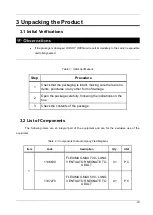
Page 23: ...nctures or any other form of damage 2 Open the package carefully following the indications on the box 3 Check the contents of the package 3 2 List of Components The following items are an integral par...

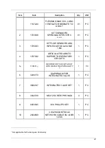
Page 24: ...E 1 6M 1 PC 4 1707302 ARTICULATED ARM TO SUPPORT RESPIRATORY CIRCUITS 1 PC 5 1 1707451 1 RESPIRATORY CIRCUIT ADULT WITH WATER TRAP STRAIGHT Y 1 1 PC 6 3206170 DIAPHRAGM FOR INTEGRATED VALVE 1 PC 7 380...

Page 25: ...ories Always use original parts and accessories to ensure the safety and efficacy of the equipment Table 3 OPTIONAL parts and accessories Item Code Description Qty UMI 1 2 1707453 2 RESPIRATORY CIRCUI...

Page 26: ...SENSOR CE 0123 1 PC 3 1704410 PULSE OXIMETER SPO2 MASIMO ADAPTER CABLE AND NEONATAL SENSOR CE 0123 1 PC 4 3201100 ADULT FLOW SENSOR AUTOCLAVABLE 1 PC 5 3201099 INFANT FLOW SENSOR AUTOCLAVABLE 1 PC 6...

Page 27: ...ator light 4 1 2 Color and touch screen LCD monitor 4 1 3 Turns and confirms button with led indicator of power supply 4 1 4 Front panel 4 1 5 Carrying handle 4 1 6 Stand 4 1 7 Wheels with brakes 4 1...

Page 28: ...nector 4 1 4 2 Nozzles for connecting proximal flow sensor lines 4 1 4 3 Distal sensor 4 1 4 4 Connector for external sensors capnograph and oximeter 4 1 4 5 External auxiliary pressure reading nozzle...

Page 29: ...on 1 Back view of Fleximag Max 700 model 2 Only for Fleximag Max 500 and Fleximag Max 700 models 4 2 7 Input for external power supply 4 2 8 Input for electrical energy 4 2 9 Fuse Holders 4 2 10 Water...

Page 30: ...30 4 3 View from the bottom of the display 4 3 1 Standard HDMI connector 4 3 2 Standard USB Connectors 4 3 3 Standard RJ 45 Ethernet Connector 4 3 4 Standard RS 232 connector 4 3 4 4 3 2 4 3 1 4 3 3...

Page 31: ...bolt and wrench that came with the equipment to screw the wheel base to the ventilator module 2 Position the diaphragm in the expiratory branch on the integrated valve in the position shown in the fi...

Page 32: ...32 OK Item Assembly Sequence Image Check that the lever is fixed 3 Attach the articulated arm to the transport handle and rotate the handle to secure...

Page 33: ...ct the patient circuit in the inspiratory and expiratory branches of the integrated valve and position on the articulated arm according to the image 5 Connect the flow sensor A Envitec Distal Sensor C...

Page 34: ...right Connect the flow sensor to the patient s respiratory circuit after the Y Connect the other end of the proximal sensor line to the flow sensor in the position shown in the figure on the right The...

Page 35: ...OK Item Assembly Sequence Image 6 When using a humidifier connect the inspiratory branch to the humidifier as shown in the figure If a heated humidifier is used it shall comply with ISO 80601 2 74 20...

Page 36: ...ng the IRMA CO2 sensor connect the airway adapter to the IRMA CO2 sensor Connect the IRMA CO2 sensor just after the proximal flow sensor or directly to the Y connector Connect the cable to one of the...

Page 37: ...gainst viruses and bacteria mount it according to the image Only use filters specified by MAGNAMED 9 If respiratory circuit is to be used for NON INVASIVE VENTILATION NIV or NIV Noninvasive Ventilatio...

Page 38: ...VASIVE VENTILATION NIV or Non Invasive Ventilation using the mask and without the filter mount it according to the image 11 If the respiratory circuit is to be used for NON INVASIVE VENTILATION NIV or...

Page 39: ...ccording to the image 13 If using a HEPA filter connect the filter between the expiratory branch of the integrated valve and the expiratory branch of the patient s circuit 14 If you want to use the ox...

Page 40: ...wer supply 16 Connect the compressed air hoses and O2 as indicated according the ventilator model Input pressures exceeding the specified limit can damage the equipment The hoses shall comply with ISO...

Page 41: ...ipment for the next use During the recharge of the internal batteries the performance of the equipment is not affected If the equipment remains unplugged from the electrical network for a period of mo...

Page 42: ...oad between 50 and 20 Medium priority Low battery Equipment operating on battery with load below 20 High priority Low battery Equipment connected to electrical network and battery charging No alarm 5...

Page 43: ...nnection if applicable The ventilator can be used on battery for up to 210 minutes continuously under normal ventilation conditions If LOW BATTERY alarm occurs IMMEDIATELY connect the ventilator to th...

Page 44: ...conditions presented STPD or BTPS If you have opted for the proximal sensor make sure it matches the type of patient selected neonatal pediatric or adult Only one type of external distal OR proximal...

Page 45: ...aker test under the risk of malfunctioning of the priority alarms during ventilation Always perform the autotest procedure before connecting the ventilator to a patient The autotest checks all importa...

Page 46: ...of the tests you must enter the RESTRICTED menu The restricted menu is accessible only with a password Once the autotest process is complete press VENTILATION to go to the ventilation screen Position...

Page 47: ...ncel and view the results individually This menu displays the air pressure O2 information date and time of the last test performed 6 2 1 3 Calibration In this menu it is possible to perform the calibr...

Page 48: ...tance that the equipment will be from the clinicians 6 2 1 7 Advanced In this menu you can adjust time and O2 concentration inspiratory and expiratory hold time keypad lock time alarm mute time type o...

Page 49: ...dal volume However to obtain the best current volume is important to know the ideal weight for each patient It is possible to obtain the ideal weight for pediatric and adult patients according to sex...

Page 50: ...alue using the turns and confirms button To confirm the set value press the button corresponding to the alarm again or press the turn and confirm button ENTER In this menu it is also possible to set t...

Page 51: ...and post aspiration of airway secretion procedures and is available in all ventilatory modes Use with an aspiration catheter may be performed in any mode and does not require a specific adjustment 6...

Page 52: ...MV Vti Pplat Pmean I E Ti Te Vte sp MV sp RR sp Ti Ttot RSBi WOBi Ri Re C dyn C stat Leakage Leakage F Tc E iPEEP O2 consumption Driving Pressure C Bargraph D Lung E Loops PxV PxF VxF VxCO2 VxFCO2 6...

Page 53: ...V is available for all ventilatory modes WARNING The default values are only an initial reference Readjust ventilation parameters as required by the patient Use the appropriate mask for each type of p...

Page 54: ...be Wrong selection of the endotracheal tube type or gauge can cause injury to the patient In the Tube Compensation window select the intubation mode and then adjust the endotracheal diameter and compe...

Page 55: ...r CPAP mode without pressure support delta PS 0 The patient should then perform successive breaths extending the inspiratory phase to the maximum and then exhale slowly to the maximum extent possible...

Page 56: ...rapped volume is only available for assisted controlled modes An unwanted volume of air may eventually become trapped in the lungs in cases of pulmonary hyperinflation or when the interval between bre...

Page 57: ...system Locks or unlocks the touch screen When the display commands are locked press this key to unlock them IMMEDIATELY To lock again simply press this key once or wait for some time without touching...

Page 58: ...l sensor oximeter or capnograph is connected The monitored parameter display option is still available where up to 24 of the 36 monitored parameters are displayed 6 3 17 Ventilation Mode Setting Area...

Page 59: ...tings of the current ventilator mode 6 3 17 2 Adjusting ventilatory modes To change or reconfigure a ventilatory mode simply touch the button that indicates the active mode in the upper right corner o...

Page 60: ...button To cancel the settings and to continue with the previous settings including the ventilatory mode simply press the CANCEL button This way the ventilator will ignore the settings made on this sc...

Page 61: ...n or restricted on the ventilator home screen 6 5 Automatic compensation of the respiratory circuit For volumes and pressures delivered and monitored leaks are always considered because of circuit com...

Page 62: ...alarm Alteration of the patient s respiratory mechanics Establish adequate parameters for ventilatory support Obstruction in the expiratory branch of the respiratory circuit or in the integrated valve...

Page 63: ...and redo the autotest No maneuvers available Neonatal patient selected Maneuvers available only for pediatric and adult patients Equipment in standby mode Press the STAND BY button for 2 seconds to r...

Page 64: ...all be cleaned with a clean soft cloth moistened with the enzymatic detergent Make sure that the equipment is turned off to perform cleaning of the display Make sure that no residue builds up in the e...

Page 65: ...dehyde hypochlorite chlorinated hydrocarbonates aromatic hydrocarbonates inorganic acids and quaternary ammonium compounds Never use saline solutions especially sodium hypochlorite bleach and saline d...

Page 66: ...connector cable and wait 30 minutes 2 Immerse the sensor in 70 ethanol solution for 1 hour 3 Allow to dry naturally for 30 minutes in the environment before reassembly The distal flow sensor must not...

Page 67: ...sive solvents to clean the oximeter These substances attack the device s materials and may result in its failure Inaccurate measures may be caused by o Incorrect sensor application or use o Significan...

Page 68: ...s Do not use alcohol to clean plastic parts Do not immerse the equipment in any liquid 8 4 1 Steam Sterilization The following accessories shall be sterilized in hot steam 135 C for 5 minutes Table 6...

Page 69: ...age or signs of wear should be replaced to prevent use Packaging of non sterile devices breathing circuits expiratory valves and connectors is designed to keep these products at the proper cleaning le...

Page 70: ...hod Neutral Enzimatic Detergent 70 Alcohol Steam Sterilization 135 C for 5 min Ventilator surface x x Touch screen x Silicone pressure line Integrated valve Diaphragm x Proximal Flow Sensor Adu Inf an...

Page 71: ...aintenance only with the authorized Magnamed Service Before sending the equipment to the service technician observe the cleaning and disinfection process RIGOROUSLY 9 1 Verifications The following ver...

Page 72: ...x x x x x x x LI ION Battery Pack x x x x O2 cell galvanic x x x x Disposal of equipment x 9 3 Consumable items Table 9 Consumable items replacement ITEM Period Silicon line 2 years or after 50 hot s...

Page 73: ...he internal batteries shall be performed by trained and qualified personnel 9 5 Water Collectors with Coalescing Filter Do not expose the filter container to non polycarbonate compatible materials Rep...

Page 74: ...h filter is used to protect the equipment To protect the patient from bacteria and virus contamination use the HEPA filter as specified in chapter 10 29 The mesh filter is used to protect the equipmen...

Page 75: ...ginal manufacturer is 10 000 hours at 100 O2 i e greater than one year of continuous use However we recommend switching during preventive maintenance on a 24 month or 10 000 hour schedule whichever co...

Page 76: ...76 measurement accuracy...

Page 77: ...done in a potentially dangerous manner considering the nature of the substances the part of the body involved and the mode of application in this case fall under Class III 10 1 5 FDA Class II Accordi...

Page 78: ...62366 2007 EN 62366 2008 Medical devices Application of usability engineering to medical devices EN ISO 17665 1 2006 Sterilization of health care products Moist heat Part 1 Requirements for the devel...

Page 79: ...age1 a Temperature 20 to 75 C b Barometric Pressure 500 to 1200 cmH2O c Relative air humidity non condensing 5 to 95 Lifetime Fleximag Max 300 Fleximag Max 500 Fleximag Max 700 10 years 1 Permissible...

Page 80: ...al DC power supply 3 Item Specification Tolerance Power supply 1 Voltage 12 to 15 VDC 10 Current 11 5 A 1 OPTIONAL external power supply It is not possible to recharge the internal batteries of the eq...

Page 81: ...work port Video output connector Standard connector HDMI Standard USB connector Used to transfer print screen trends logs and recordings to an external USB flash memory storage device flash drive It c...

Page 82: ...s a valid Internet Protocol IP Communication is done through the TCP protocol in the IT network For communication with the electronic health recorder an appropriate communication protocol shall be imp...

Page 83: ...Compressed air and oxygen inlet pressure 200 to 600 kPa 29 to 87 psi Respiratory circuit According to ISO 5367 2014 Input pressures exceeding the specified limit can damage the equipment For inlet pr...

Page 84: ...Solenoid Valve On Off NIF 26 Measurement point proximal pressure differential 10 x 5 100 psi Solenoid Valve Nebulizer 27 Respiratory circuit 15 O2 concentration cell 28 HME filter 16 Internal Flow Se...

Page 85: ...C The velocity of the gas passing through the sensor determines the rate of heat transfer between the sensor and the gas This heat transfer rate is translated into a voltage necessary to maintain the...

Page 86: ...l Material MABS 10 8 Proximal Flow Sensor Specifications Table 18 Proximal Flow Sensor General Specifications ADULT General specifications Intended use Measure the inspired and expired flow of the pat...

Page 87: ...ecommended flow rate 0 1 10 lpm Data sampling rate 7 Hz Method for calculating the gas level reading Simple moving average SMA of 64 positions acquired every 140ms Respiratory rate The Respiratory Rat...

Page 88: ...0 mV Response time 90 8 s Accuracy 0 2 Linearity 0 2 Data sampling rate 7 Hz Method for calculating the gas level reading Simple moving average SMA of 64 positions acquired every 140ms Respiratory rat...

Page 89: ...curs after release of the pre set tidal volume at given velocity through the flow or ratio or inspiratory time Adjusted Parameters VOLUME RATE FLOW or RATIO or INS TIME PEEP O2 CONCENTRATION LIMIT PRE...

Page 90: ...ported in the status and message area The patient s inspiratory effort detection for synchronization occurs at any point in the expiratory time If the patient makes inspiratory efforts and the trigger...

Page 91: ...ckup 1 1 Whenever the set apnea time is reached the ventilator triggers a ventilator cycle the setting of which is based on the current mode settings Once all ventilation parameters are set on the ven...

Page 92: ...re properly adjusted the ventilatory mode becomes assisted controlled In this situation the monitored respiratory rate may be significantly greater than that adjusted 4 The rise time of the pressure c...

Page 93: ...ected by the operator Usually by observing the flow curve you see a peak of flow that decreases as time goes by Adjusted Parameters INSPIRATORY PRESSURE RATE INSPIRATORY TIME PEEP O2 CONCENTRATION FLO...

Page 94: ...spiratory cycle is reported in the status and message area of the screen The patient s inspiratory effort detection for synchronization occurs at any time during the expiratory time The default values...

Page 95: ...cycling happens according to the adjusted inspiratory time At each cycle the ventilator adjusts the pressure limit 5 cmH2O up according to the tidal volume distributed in the previous cycle until the...

Page 96: ...configured trigger Detection of the patient s window of effort for synchronization begins in the last quarter of the period of controlled ventilation 7 Volume reached Upon reaching the pressure limit...

Page 97: ...ons return The transition between inspiration and expiration in the mandatory cycles occurs after release of the pre set tidal volume at given velocity through the flow or ratio or inspiratory time In...

Page 98: ...e of its maximum reached value 5 The percentage of peak flow at which inspiratory phase cycles to the expiratory phase is programmable Rise time TRISE is also applied to support pressure see PCV 6 If...

Page 99: ...ventilation parameters as required by the patient The monitored respiratory rate may be higher than the adjusted respiratory rate as the patient may breathe spontaneously during the mandatory ventila...

Page 100: ...cursions return The transition between inspiration and expiration in the mandatory cycles occurs after release of the pre set tidal volume at given velocity through the flow or ratio or inspiratory ti...

Page 101: ...rcentage of its maximum reached value 5 The percentage of peak flow at which inspiratory phase cycles to the expiratory phase is programmable Rise time TRISE is also applied to support pressure see PC...

Page 102: ...reference only Readjust ventilation parameters as required by the patient The monitored respiratory rate may be higher than the adjusted respiratory rate as the patient may breathe spontaneously durin...

Page 103: ...me and thus the volume of inspiratory air Cycle transition between inspiration and expiration occurs by flow as it falls to a certain percentage of its maximum reached value If the support pressure va...

Page 104: ...occurs by flow as soon as it falls to a certain percentage of its maximum reached value 6 If the patient goes into apnea after TAPNEIA s the ventilator will present this condition through an alarm in...

Page 105: ...105 1 and 2 They represent spontaneous cycles 1 If the patient does not breathe after the time for apnea the ventilator enters the backup and activates the apnea alarm...

Page 106: ...certain percentage of its maximum reached value Without spontaneous breathing DualPAP is similar to the controlled pressure mode differing from this by adjusting the times Superior T and Inferior T r...

Page 107: ...107 DualPAP Two stage positive pressure ventilation...

Page 108: ...that reference pressure and PS The default values are initial reference only Readjust ventilation parameters as required by the patient In the absence of spontaneous cycles when in DualPAP adjust the...

Page 109: ...expiration occurs by flow as it falls to a certain percentage of its maximum reached value Without spontaneous breathing APRV is similar to the controlled pressure mode differing from this by adjusti...

Page 110: ...ief The support pressure PS is a value above the superior or inferior pressure Therefore the maximum support pressure will be the sum of that reference pressure and PS The default values are initial r...

Page 111: ...alarm will be displayed On the other hand if the set apnea time is reached the backup ventilation will be activated The onset of inspiration occurs when the patient makes an effort that is recognized...

Page 112: ...ion will be activated The onset of inspiration occurs when the patient makes an effort that is recognized by the ventilator according to the adjusted trigger If the backup is active and the patient go...

Page 113: ...iration will occur according to the set apnea time Cycle transition between inspiration and expiration occurs by flow as it falls to a certain percentage of its maximum reached value Adjusted Paramete...

Page 114: ...e ventilator triggers a ventilator cycle the setting of which is based on the current mode settings 10 12 14 VG VG Guaranteed Volume Ventilation Description Available only for neonatal patient this ve...

Page 115: ...THERAPY Description Available for all patient types this special mode offers continuous O2 flush according the O2 concentration and flow set This mode requires a compatible interface Adjusted Paramet...

Page 116: ...Table 23 Accuracy of settings Item Parameter Accuracy 1 2 1 Tidal volume All range 1 4 mL 15 of set volume 2 Inspiratory pressure 2 cmH2O 4 of set pressure 3 PEEP 2 cmH2O 4 of set PEEP 4 FiO2 5 2 5 of...

Page 117: ...Neonatal 1 2 0 to 10 0 0 1 mL 10 to 99 1 Pediatric 10 to 100 5 100 to 300 10 Adult 100 to 1000 10 1000 to 3000 50 2 Respiratory rate 2 3 0 to 200 Neonatal 0 to 200 1 rpm Pediatric 0 to 200 1 Adult 0...

Page 118: ...45 1 cmH2O 17 Superior Time DualPAP APRV 0 10 to 59 8 0 20 to 0 70 0 01 s 0 70 to 1 00 0 05 1 00 to 59 80 0 10 18 Inferior Time DualPAP APRV 0 20 to 59 9 0 20 to 0 70 0 01 s 0 70 to 1 00 0 05 1 00 to...

Page 119: ...NATAL proximal flow sensor and in VG mode 2 Respiratory rate 0 zero will only be reached in spontaneous modes with triggers and backup off 3 The minimum and maximum values of rate and I E ratio depend...

Page 120: ...lat 0 to 120 cmH2O 1 2 cmH2O 4 of reading PEEP 0 to 120 cmH2O 1 2 cmH2O 4 of reading Intrinsic PEEP iPEEP 0 to 99 9 cmH2O 1 2 cmH2O 4 of reading Measured Flow 4 180 to 180 L min 1 50mL min 10 of readi...

Page 121: ...ure 0 to 120 cmH2O 1 2 cmH2O 4 of reading Elastance 0 to 100 cmH2O L 1 1cmH2O L 10 of reading Leakage flow 4 0 0 to 19 9 L min 0 1 50mL min 10 of reading 20 to 180 L min 1 Percentage leakage 4 0 to 10...

Page 122: ...following conditions o Reuse of single use accessories o Incorrect sensor uses for patient type o Secretion in the circuit and flow sensor o Leakage in the circuit o Oxygen cell and flow sensor not ca...

Page 123: ...rs to the occurrence of the lesion and not to its manifestation 2 There is potential for the event to develop over a period usually not enough for manual corrective action 3 There is potential for the...

Page 124: ...ustable alarms Alarm Adjustment Limit Default Values 1 Unit Neonatal Pediatric Adult Maximum Pressure OFF 0 to 120 High 30 30 40 cmH2O Low OFF OFF OFF PEEP OFF 0 to 80 High 10 15 20 cmH2O Low OFF OFF...

Page 125: ...ALARM OFF Automatic alarm adjustment is based on the monitored values so it can only be used when the ventilator is NOT in the STAND BY mode and preferably when the parameters are stable 10 18 2 Venti...

Page 126: ...the alarm value set as its lower limit FLOWAIR VERY HIGH TEMPERATURE 1 1 second Indicates that the temperature of the FlowAir system is too high FLOWAIR FAILURE 1 1 second Indicates a failure in the...

Page 127: ...ot reach the alarm value set as its lower limit LOW BATTERY 1 second The battery is less than half of its total capacity INVERTED I E RATIO 1 second It indicates that the ratio I E is inverse i e the...

Page 128: ...ert Messages In the event of one or more ventilator related alerts the following messages may be displayed Table 33 Alert messages Message Delay Description ASSIST TRIGGER FLOW 1 second Indicates the...

Page 129: ...respective priorities Table 34 High priority alarms High priority alarm Delay Description HIGH EtCO2 3 seconds The expired CO2 rate exceeded the alarm value set as the upper limit of EtCO2 LOW EtCO2...

Page 130: ...y connected CO2 CHANGE ADAPTER 3 seconds Indicates that the IRMA CO2 sensor must be replaced CO2 REPLACE IRMA 3 seconds Indicates that there is a problem with Hardware and should be replaced CO2 RESTA...

Page 131: ...ndicates that the sensor is not on the patient s finger SPO2 NO SENSOR 3 seconds Indicates that the sensor is not connected SPO2 LOW PERFUSION 3 seconds Indicates signal quality too low SPO2 NO PULSE...

Page 132: ...safety It may be dangerous if different alarm pre configurations are used for the same or similar equipment in the same area such as an intensive care unit or cardiac surgery room 10 18 6 Alarm Testi...

Page 133: ...volume below the volume adjusted in the mode parameters To test the low volume alarm set the alarm s lower limit volume above the volume adjusted in the mode parameters 10 18 6 4 No AC power alarm Rem...

Page 134: ...larm 10 18 6 10 Minute volume alarm To test the high minute volume alarm set the alarm s upper limit minute volume below the monitored in the equipment To test the low minute volume alarm set the alar...

Page 135: ...upper limit heart rate below the monitored in the equipment To test the low heart rate alarm set the alarm s lower limit heart rate above the heart rate monitored in the equipment 10 18 6 16 SpO2 ala...

Page 136: ...ce specifications Respiratory circuit Flow L min Resistance hPa or cmH2O 1 Circuit Circuit Flow Sensor Circuit Flow Sensor HME Filter Circuit Flow Sensor CO2 Sensor HME Filter Neonatal 2 5 0 3 0 85 1...

Page 137: ...mes first Equipment Inspection 5 000 hours or 12 months whichever comes first Calibration of equipment 5 000 hours or 12 months whichever comes first 10 22 IRMA CO2 Sensor Specifications Table 45 IRMA...

Page 138: ...specified Accuracy and Sensor Error Method to calculate the gas level reading The highest concentration of CO2 during one breathing cycle with a weight function applied to favor values closer to the e...

Page 139: ...apor interference Effects of gas and vapor interference Gases or Steam Gas Level CO2 N2O 60 vol 1 and 2 HAL 4 vol 1 ENF ISO SEV 5 vol 8 of the read measurement 3 DES 15 vol 12 of the read measurement...

Page 140: ...formance specifications Table 53 Environmental specifications Specification Criteria Functional SpO2 Pulse Rate bpm Perfusion index PVI Display Range 0 0 100 0 25 240 bpm 0 02 20 0 0 100 Calibration R...

Page 141: ...hnical alarm condition to indicate failure of the air and oxygen network limiting the reverse flow between the gas port to values below 100 mL h ensure the accuracy of the oxygen level within the spec...

Page 142: ...Class A The Fleximag Max is suitable for use in all establishments other than domestic and those directly connected to the public low voltage power supply network that supplies buildings for domestic...

Page 143: ...feeding should be at levels characteristic of a typical location in a typical hospital or commercial setting Note UT is the a c mains voltage prior to application of the test level The Fleximag Max is...

Page 144: ...aration distances between portable and mobile RF communications equipment and the Fleximag Max The Fleximag Max is intended for use in an electromagnetic environment in which radiated RF disturbances...

Page 145: ...z Deviation from 5kHz 28 704 to 787 710 745 780 Pulse 217 Hz 9 800 to 960 810 870 930 Pulse 18 Hz 28 1 700 to 1 990 1 720 1 845 1 970 Pulse 217 Hz 28 2 400 to 2 570 2 450 Pulse 217 Hz 28 5 100 to 5 80...

Page 146: ...ting any equipment to these outlets subject the system to a complete leakage current test in accordance with IEC 60601 1 The electromedical system operator shall not touch non medical electrical equip...

Page 147: ...onatal connection 15 mm Resistance 0 3 mbar L s 1 Use only respiratory circuit specified by MAGNAMED with local registration and CE mark Use respiratory circuit suitable for patient type to avoid exce...

Page 148: ...0 29 HEPA Filter In order to avoid cross contamination a HEPA filter following the specifications given below with local registration and CE mark shall be used Table 58 HEPA filter specification Speci...

Page 149: ...he breathing circuit allowing XTP windows positioned on the sides of the sensor to measure gas concentrations Running on a standard low voltage continuous electric voltage the sensor is designed to me...

Page 150: ...dow as soon as the sensor is identified and ready for use It may take a few seconds until the sensor is ready for the zeroing process Zeroing shall be done by connecting an airway adapter to the senso...

Page 151: ...strument 11 4 Important Notices The IRMA CO2 sensor shall be operated exclusively by trained and authorized medical personnel The sensor shall not be used with flammable anesthetic agents Airway adapt...

Page 152: ...s produced by Masimo The sensor shall not come in direct contact with the patient during use Do not connect the airway adapter between the endotracheal tube and the respiratory circuit elbow as this c...

Page 153: ...infrared LED emitting diodes on the oximetry sensors serve as light source the photodiode serves as a photodetector Traditionally pulse oximetry assumes that all pulsations in the light absorption si...

Page 154: ...660 S 905 x R which is the same ratio as the traditional pulse oximeter The equation for reference noise is based on the value of R at the value sought to determine SpO2 The MS board software scans al...

Page 155: ...r may perform the maintenance procedures described in the product manual Contact Magnamed service for oximeter repairs As with all medical equipment position the cable on the patient in order to reduc...

Page 156: ...ons for use for reusable Masimo LNOP LNCS sensors Do not use damaged cables Do not immerse the patient cable in water solvents or cleaning solution patient cables are not waterproof Do not sterilize b...

Page 157: ...and performance of the ventilator DO NOT OPERATE the equipment if it is not operating according to the specifications contained in this operating manual Before sending the equipment to the service te...

Page 158: ...ids e g breathing circuit and that are potentially contaminated are called semi critical and must be endure a high level disinfection or sterilization process before disposal at the end of their usefu...

Page 159: ...mm in diameter or more and protected against falling drops EC Conformity Indicates that the equipment complies with the European Council directive 93 42 EEC for medical equipment Authorized Representa...

Page 160: ...a physician Consult documentation that came with the product 15 2 Symbols used in packaging and labeling Table 61 Symbols used in packaging and labeling Symbol Description Fragile Direction of upper...

Page 161: ...Reprocessing is prohibited Part or accessory not supplied sterile Sterilize before use Expiration date Do not use if packaging is damaged Manufacturer s Catalog Number Manufacturer serial number Manu...

Page 162: ...NIV or VNI Noninvasive Ventilation O2 Concentration of 50 to 100 O2 for a certain time O2 100 100 O2 concentration for a certain time MANUAL CYCLE or INSP MANUAL Manual Cycle trigger INSP HOLD Inspir...

Page 163: ...ssure setting Pr Control in pediatric or adult patients refers to a relative pressure that is it adjusts the pressure value ABOVE PEEP The resulting inspiratory pressure will be the sum of the pressur...

Page 164: ...d in parts applied to Fleximag Max such as silicone and polysulfide have been widely used in the medical field over time with no effects related to toxicity or tissue effects ensuring their biocompati...

Page 165: ...se and whose preventive maintenance and replacement of parts and repairs are carried out according to the instructions in the Product Operation Manual by personnel authorized by the manufacturer The w...

Page 166: ...19 Training To request training contact Magnamed Product Specialist who will direct you to the nearest authorized representative The training is performed in loco and is expected to be executed in 1 h...

Page 167: ...0 BACK VIEW FLOWAIR YES NO YES AIR PROPORTIONAL VALVE YES YES NO Alarm FLOWAIR Very High Temperature YES NO YES Alarm FLOWAIR HIGH TEMPERATURE YES NO YES Alarm FLOWAIR Failure YES NO YES Alarm LOW AIR...

Page 168: ...sil Tel Fax 55 11 4615 8500 E mail magnamed magnamed com br Website www magnamed com br CNPJ 01 298 443 0002 54 State registration 149 579 528 111 European Representative CMC Medical Devices Drugs S L...

Reviews: