background image

7

SAFETY GUIDELINES

This fixture is a sophisticated piece of electronic equipment. To guarantee smooth operation, it is 
important to follow all instructions and guidelines in this manual. Magmatic Effects is not responsible 
for injury and/or damages resulting from the misuse of this fixture due to the disregard of the informa-
tion printed in this manual. Only qualified and/or certified personnel should perform installation of this 
fixture and only the original rigging parts included with this fixture should be used for installation. Any 
modifications to the fixture and/or the included mounting hardware will void the original manufac-
turer’s warranty and increase the risk of damage and/or personal injury.

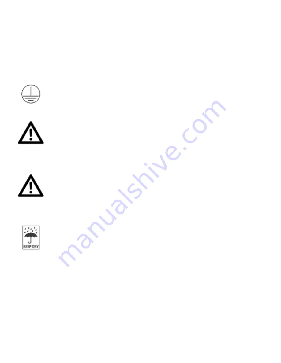
PROTECTION CLASS 1 - FIXTURE MUST BE PROPERLY GROUNDED.

THERE ARE NO USER SERVICEABLE PARTS INSIDE THIS UNIT. DO 

NOT ATTEMPT ANY REPAIRS YOURSELF. DOING SO WILL VOID 

YOUR MANUFACTURER’S WARRANTY. DAMAGES RESULTING FROM 

MODIFICATIONS TO THIS DEVICE AND/OR THE DISREGARD OF 

SAFETY INSTRUCTIONS AND GUIDELINES IN THIS MANUAL VOID THE 

MANUFACTURER’S WARRANTY AND ARE NOT SUBJECT TO ANY WARRANTY 

DO NOT PLUG THIS UNIT INTO A DIMMER PACK

DO NOT REMOVE THE COVER UNDER ANY CONDITIONS

KEEP UNIT IN AN UPRIGHT POSITION

NEVER OPERATE THIS UNIT WITH THE COVER REMOVED

UNPLUG FROM POWER DURING LONG PERIODS OF NON-USE

ENSURE TANK IS EMPTY BEFORE STORAGE OR TRANSPORT

DO NOT MOVE WHEN FILLED WITH FLUID

DISCONNECT POWER BEFORE ADDING FLUID OR PERFORMING 

MAINTENANCE

FOR USE IN INDOOR / DRY LOCATIONS ONLY

DO NOT EXPOSE DEVICE TO RAIN AND/OR MOISTURE

PLACE UNIT IN A WELL VENTILATED AREA

ALLOW 40” (100CM) ABOVE AND AROUND THE UNIT FOR PROPER 

VENTILATION.

Summary of Contents for THERMA TOUR 800

Page 1: ...User Manual THERMA TOUR 800 US SKU TST801 UPC 810008261552 ...

Page 2: ... with the use or reliance of any information contained within this document and or as a result of the improper unsafe insufficient and negligent assembly installation rigging and operation of this product DOCUMENT VERSION Duetoadditionalproductfeaturesand orenhancements anupdatedversionofthisdocument may be available online Please check www elationlighting com for the latest revision update of thi...

Page 3: ...ited Warranty USA Only 5 Warranty Returns USA Only 6 Safety Guidelines 7 Overview 9 Set Up 10 Control Panel 11 System Menu 12 Preset Mode 16 DMX Traits 17 Trouble Shooting Cleaning Maintenance 18 Specifications 19 Dimensional Drawings 20 ...

Page 4: ... recycle whenever possible BOX CONTENTS Twist locking power cable x1 Haze outlet cap x1 CUSTOMER SUPPORT Contact MAGMATIC customer service for any product related service and support needs Also visit forums elationlighting com with questions comments or suggestions ELATION SERVICE USA Monday Friday 8 00am to 4 30pm PST 323 582 3322 Fax 323 832 9142 sales magmaticeffects com ELATION SERVICE EUROPE ...

Page 5: ...user manual D This is not a service contract and this warranty does not include any maintenance cleaning or peri odic check up During the periods as specified above Magmatic Effects will replace defective parts at its expense and will absorb all expenses for warranty service and repair labor by reason of defects in material or workmanship The sole responsibility of Magmatic Effects under this warr...

Page 6: ...ght pre paid and insured to MAGMATIC in Los Angeles CA or a MAGMATIC Authorized Service Center The RMA number must be clearly written on the outside of the return box and a brief description of the problem and the RMA number must be documented and included in the box Products returned for warranty service without an RMA number clearly marked on the outside of the package will be refused and return...

Page 7: ... CLASS 1 FIXTURE MUST BE PROPERLY GROUNDED THERE ARE NO USER SERVICEABLE PARTS INSIDE THIS UNIT DO NOT ATTEMPT ANY REPAIRS YOURSELF DOING SO WILL VOID YOUR MANUFACTURER S WARRANTY DAMAGES RESULTING FROM MODIFICATIONS TO THIS DEVICE AND OR THE DISREGARD OF SAFETY INSTRUCTIONS AND GUIDELINES IN THIS MANUAL VOID THE MANUFACTURER S WARRANTY AND ARE NOT SUBJECT TO ANY WARRANTY DO NOT PLUG THIS UNIT INT...

Page 8: ...re Do not attempt to operate this device if the power cord has been frayed crimped and or damaged Replace any damaged power cords with new cords of the same power rating Do not remove or break off the ground prong from the electrical cord This prong is used to reduce the risk of electrical shock and fire in case of an internal short Always disconnect from main power before making any connection pe...

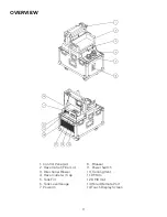
Page 9: ...2 Haze Outlet Filler Lid 3 Directional Blower 4 Haze Outlet w Cap 5 Tank Fill 6 Tank Level Gauge 7 Power In 8 Breaker 9 Power Switch 10 Cooling Vent 11 DMX In 12 DMX Out 13 Wired Remote Port 14 Touch Display Screen OVERVIEW ...

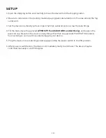
Page 10: ...he tank fill cap 4 Fill the tank only with approved ATMOSITY fluid SKU ARH and AAH only and replace the reservoir cap Never run the device on anything other than an approved MAGMATIC branded fluid as doing so can result in severe damage to your device 5 Plug the device into a matching power supply and flip the power switch to the ON position 6 After power is switched on the device is immediately r...

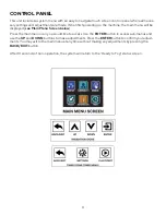
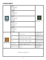
Page 11: ... Menu Screen below Press the main menu icon you would like to access Use the ENTER button to access sub menus and use the UP and DOWN buttons to make adjustments PresstheENTERbutton to confirmyouradjust ments You may exit to the main menu at any time without making any adjustments by pressing the BACK EXIT button After 10 seconds of non operation the system will return to the Ready to Fog status s...

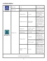
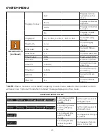
Page 12: ... the device will lock MagApp ID 0 255 0 255 0 255 0 255 MagApp IP display format is a combi nation of 4 digit 0 255 data MapApp Port 0 65535 Network port ten tative MagApp Reset Complete MagApp module signal detected within 5s reset is successful returns to MagApp Reset screen after 2s Failed try again MagApp module signal not detected after 5s reset has failed MagApp DMX Magfly On Off Enable or d...

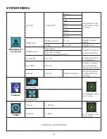
Page 13: ...ted MagRF module fre quency matching Connection Failed fails to connect within 20s Liquid LED On Off Liquid level indica tor LED switch Last State Yes No Enable or disable device s ability to stay at the last step Default Yes No Default Interface Return the device to default factory settings MANUAL Fog 100 Use triangle icon to start or stop Wind 100 TIMER Interval 0 2500s Use triangle icon to star...

Page 14: ...5 Duration 5 min Interval 5 min Fog 100 Fan 100 INFORMATION State Normal Error Shows whether device is operating normally Slot 1 Null Magfly MapApp MagRF Shows what type of module is inserted in slot 1 Slot 2 Null Magfly MapApp MagRF Shows what type of module is inserted in slot 2 Last Control LCD_auto LCD_manual DMX MagApp MagRF MagRemote Error Current method of device control MagRemote State Yes...

Page 15: ... setting Timer Dur 0 250s Current timer dura tion setting LCD Ver Vx x Current LCD ver sion Sftwr Ver Vx x Current software version NOTE When a module is not installed navigating to a sub menu related to that module s function will result in an Optional Module Not Installed message displayed on the screen MESSAGE SMALL ICONS Icons displayed after inserting MagFly module Left to right weakest to st...

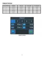
Page 16: ...16 PRESET MODE Preset Mode Duration Interval Fog Output Fan Intensity 1 40 min 20 min 100 100 2 30 min 15 min 100 100 3 20 min 10 min 100 100 4 10 min 5 min 100 100 5 5 min 5 min 100 100 PRESET SCREEN ...

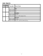
Page 17: ...17 DMX TRAITS CHANNEL VALUES FUNCTION 1 CH 3 CH 1 1 Fog 000 005 Off 006 255 On 2 Duration 000 005 Off 0s 006 255 On 1s 250s steps of 1s 3 Interval 000 005 Off 0s 006 255 On 10s 2500s steps of 10s ...

Page 18: ...tly it will require service Please contact Magmatic Effects for assistance CLEANING MAINTENANCE When storing your device be sure to store in a cool area Cover the device so that dust does not build up on the device It is highly advisable to run the machine at least once every 3 4 months when stor ing for long periods of time Long periods of inactivity can severely shorten the life of your device O...

Page 19: ...s RDM Remote DMX Control Protocol DMX DMX Channels 1 3 DMX Modes 2 On Board Timing Control 5 Factory Presets 4 Pin Wired Remote Input Touch Screen Display Manual Hazing CONNECTIONS Data Connectors 5 Pin XLR Out 4 Pin XLR Out Locking Power Connector SIZE WEIGHT Length 24 45 in 621 13mm Width 15 34 in 389 63mm Height 16 33 in 414 75mm Weight 93 lbs 42kg ELECTRICAL Power Consumption 820w Input Voltag...

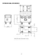
Page 20: ...20 DIMENSIONAL DRAWINGS Dimensions may not be drawn to scale ...

Page 21: ...21 ...

Page 22: ......

Reviews: