Magma BERILL TM Operation And Maintenance Manual Download Page 17


16 

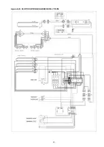
Appendix C. CHANGING THE OPERATING TEMPERATURE OF THE DISPLAY CASE 

Operating temperature is set up by changing the value of the parameters in the display case controller: 

- “

FSt

“ (pallet temperature); 

- “

Set

“ (temperature of the display case upper space). 

Note - The value of the “

Set

“ parameter must always be lower then that of the “

FSt

“ parameter to prevent 

fogging of the front glass,. 

To change the value of the “

FSt

“ parameter (upper place temperature) do the following: 
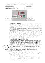
Enter the 

Programming

 menu by pressing and holding the “

set

“ button of the controller for at least 5 seconds. 

The label of the first menu folder “

CP

“ will appear on the display. 

> 5 seconds 


Use the “

Up

“ and “

Down

“ buttons to scroll through the programming menu folders until the “

FAn

“ folder  


While on the folder label “

FAn

“, press the “

set

“ button 


the first folder parameter will appear on the controller display. 

Use the “

Up

“ and “

Down

“ buttons to switch to the “

FSt

“ parameter. 


Press the “

set

“ button on the “

Fst

“ parameter and you will see its value. 


Set the new temperature value by “

Up

“ and “

Down

“ buttons  


Press the “

fnc

“ button


The entered parameter has been saved.  

Turn off and turn on the display case again, now the case will work with the newly set value of the lower heating 
temperature. 

To change the value of the "

Set

" parameter (tray temperature), it is required the following: 

Turn on the showcase. Press the “

set

“ button on the controller, “

Set

“ will be displayed on the scoreboard. 


Summary of Contents for BERILL TM

Page 1: ..._____________________________________________________________________________________________________________________________________________________________________ OPERATION AND MAINTENANCE MANUAL H...

Page 2: ...instructions contained in this manual Notice All dimensions in drawings are given in mm if not otherwise specified Illustrations may not fully correspond to the models shown in the guidelines CONTENT...

Page 3: ...f food products whose storage temperature corresponds to the temperature range of the display case 1 2 DEVELOPMENT AND STANDARDIZATION This equipment has been designed and manufactured in accordance w...

Page 4: ...containing flammable mixtures inside this appliance ATTENTION it is strictly forbidden to turn on the display case without grounding and move the display case that is under voltage Make sure that both...

Page 5: ...set of the cabinet light 12h Basic set of the cabinet light 24h kW h 24 0 24 2 47 8 48 2 Water supply data Heated water volume m 0 07 0 14 Water features type hot tap water Pressure range bar 0 1 10...

Page 6: ...nside the display case An electromagnetic valve is installed on the water filling pipe to automatically replenish the water in the reservoir The operation of the solenoid valve is controlled by an ele...

Page 7: ...r 5 2 Automatic replenishment of water in the reservoir Automatic replenishment of the reservoir is carried out by opening the solenoid valve at the signal of the sensor MINIMUM LEVEL The WATER FILLIN...

Page 8: ...al codes they can be viewed by scrolling Up and Down buttons E1 sensor 1 Error thermostat sensor Pb1 upper space sensor E2 sensor 2 Error Pb2 sensor reservoir sensor E3 sensor 3 Error sensor Pb3 AH1 A...

Page 9: ...e equipment to prevent possible damage for example from the impact of a trolley a polisher a loader etc 6 3 DISPLAY CASE CONNECTION TO THE WATER SUPPLY A plumbing flexible hose with G nuts is employed...

Page 10: ...econd there should be a click from the opening of the electromagnetic water filling valve and the indicator lamp WATER FILLING should light up 3 Check the heating of each heating element of the upper...

Page 11: ...EFFORT AND SKEWING OF THE GLASS MAY OVERLOAD THE EDGE OF THE GLASS AND AS A RESULT DESTROY IT 7 2 TURNING ON THE DISPLAY CASE Turn on the display case only after carrying out all preparatory works ful...

Page 12: ...mperature in the display case tray The electronic controller manages Automatic control and maintaining of the operating temperature within the specified limits The procedure for changing the operating...

Page 13: ...er supply to guarantee the absence of an electric current in the system Purpose of cleaning is to remove pathogenic microorganisms on external parts and interiors of the case and to maintain physical...

Page 14: ...d should be disposed of in compliance with local regulations 11 2 END OF THE EQUIPMENT S LIFE CYCLE At the end of a useful life of the equipment we recommend the following Make it unserviceable for ex...

Page 15: ...14 Appendix A ELECTRIC WIRING DIAGRAM BERILL TM 125...

Page 16: ...15 Appendix B ELECTRIC WIRING DIAGRAM BERILL TM 250...

Page 17: ...ll appear on the display 5 seconds Use the Up and Down buttons to scroll through the programming menu folders until the FAn folder While on the folder label FAn press the set button the first folder p...

Page 18: ...the display case again now the case will work with the newly set temperature value of the upper space Find below an example of a sequence of actions to change the value of the FSt parameter from 60 C...

Page 19: ...in turning off the water filling by deactivating the MINIMUM LEVEL signal dOd Door switch switches off loads n 2 flag Block the upper heating by the signal MINIMUM LEVEL DISPLAY page labeled diS ddd...

Page 20: ...ld and similar electrical appliances Safety Part 2 49 Particular requirements for commercial electric appliances for keeping food and crockery warm is in conformity with the Directives 2014 30 EU Elec...

Reviews: