


18
NOTE
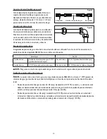
: The triple burner has only two injectors, one injector mounted in the center and another mounted below
the cover plate� To access the second injector, remove the two screws and the cover plate�
24” Burner and Orifice Characteristic Table
Refer to the following chart for correct gas orifice spud placement�
IMPORTANT
: Save the orifices removed from the appliance for future use�
Burner
Position
Orifice
Gas
Pressure
Rate
Diam� (mm)
Type
[i�w�c]
[BTU/h]
Auxiliary
Front R
0�9
NG
4”
5000
0�58
LP (Propane)
10”
5000
Semi-Rapid
Rear L
1�17
NG
4”
6859
0�75
LP (Propane)
10”
6859
Triple
Front L
0�93 + 1�82
NG
4”
17357
1�14 + 0�56
LP (Propane)
10”
15000
Rapid
Raer R
1�6
NG
4”
6859
1�03
LP (Propane)
10”
6859
24” SERIES OF PRODUCTS
Gas Type: Natural Gas 4” Test Point Pressure
Burner
Injector Size (mm)
Burner Rating (BTU)
Large
0�99 mm x 5
17400
Small
1�29 mm
6900
Tiny
1�10 mm
5000
Top Burner
1�40 mm
7900
Bottom Burner
1�70 mm
10700
Gas Type: LPG 10” Test Point Pressure
Burner
Injector Size (mm)
Burner Rating (BTU)
Large
0�56 mm x 5
15000
Small
0�80 mm
6500
Tiny
0�70 mm
5000
Top Burner
0�85 mm
7900
Bottom Burner
1�10 mm
10800
Summary of Contents for MCSRG24S
Page 20: ...20...