


V1.0
– Feb-12
User’s Manual
Page 26 of 35
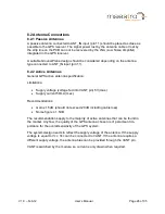
8.2 Antenna Connections
8.2.1 Passive Antennas
A passive antenna connected to ANT_IN input (pin 11) should be placed as close as
possible to the GPS receiver. The signal power lost by the antenna cable or lost by
the strip line on the PCB can not be recovered by the LNA (Low Noise Amplifier)
integrated in the GPS receiver.
A suitable Ground-Plane design should be considered depending on the antenna
type connected to ANT_IN input (pin 11).
8.2.2 Active Antennas
General GPS active antenna specification:
Limitations:
Supply voltage (voltage fed into VANT pin) 5V (max.)
Supply current 50mA (max.)
Recommendations:
Gain ≥ 15dB (should not exceed 20 dB including cable loss)
Noise figure ≤ 1.5dB
The recommendations apply to the majority of active antennas that can be found in
the market. Anyhow, the quality of the GPS antenna chosen is of paramount im-
portance for the overall sensitivity of the GPS system.
The system design needs to reflect the supply voltage of the antenna. If the supply
voltage is equal to Vcc, Vcc can be connected to VANT. If the antenna requires a
different supply voltage, the antenna bias can be provided through the VANT pin.
VANT is switched by the module, so current is only drawn when required.