

Installation and Operation
Installing the software
Insert the MadgeTech 4 Software USB flash drive into an available USB port on the PC. If
the autorun does not appear, locate the drive on the computer and double click
Autorun.
exe
. Follow the instructions in the Wizard.
Installing the Interface Cable
- IFC200: Insert the device into a USB port. The drivers will install automatically.
Connecting the Data Logger
- Launch the MadgeTech 4 Software. Plug one end of the interface cable into the IFC200
and the opposite end into the data logger.
Starting the Data Logger
- Click
Device
tab in the MadgeTech 4 Software.
- The data logger should appear in the connected devices list.
- Choose the desired
Start
method and a
Reading Rate
suitable for your application.
- Enter in any other desired parameters and click
Start
.
- Wait until the status of the connected data logger displays “Running” to confirm it has
started successfully.
- Disconnect the data logger from the interface cable and place it in the environment to
measure.
Note: The device will stop recording data when the end of memory is reached or the device
is stopped. At this point the device cannot be restarted until it has been re-armed by the
computer.
Downloading data from a data logger
- Connect the data logger to the interface cable on the PC.
- Click on the device in the connected devices list, right click and select
download.
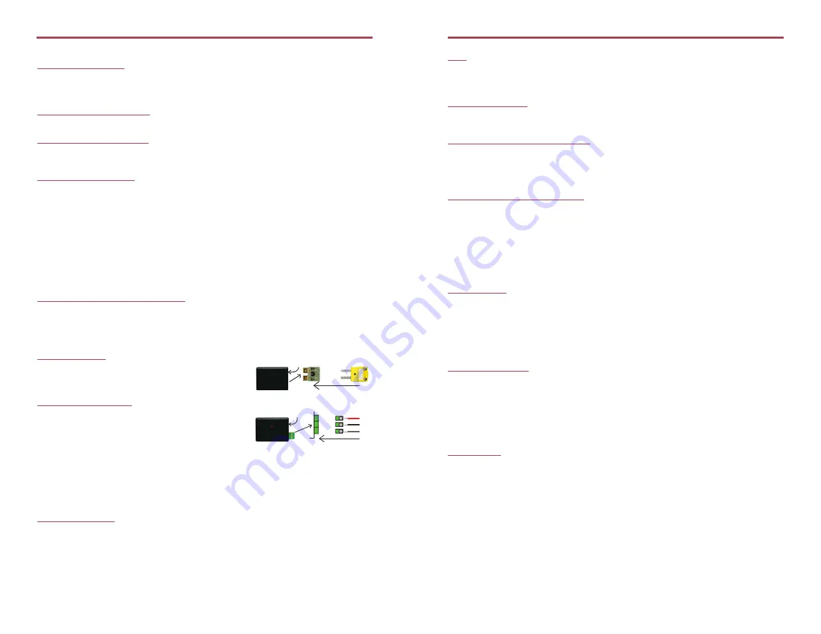
Wiring the Data Logger
MP Model Wiring
The standard connector is the SMP connection which
allows for the user to insert a subminiature thermocouple
plug into the connector on the device.
ST and TB Model Wiring
The TC101A-ST and TC101A-TB have a three position
removable screw terminal. This enables the data logger
to be connected to most 3-wire thermocouples with lead
wires.
Note: Be sure to connect the thermocouple with the right polarity as marked on the device case.
The TC101A-ST and TC101A-TB have the ability to shield the thermocouple with the
ground connection. When using a 2-wire thermocouple, leave the ground input unconnected.
Product Notes
Thermocouple Type
To change the thermocouple type:
- Select the Device Menu, then Identify Device and Read Status.
- Select the Device Detail tab, then Thermocouple Type.
- Click on the
Change
button in the Thermocouple Type window.
- Select the correct thermocouple type from the drop down list.
- Click on the
Save
button to store the thermocouple type in the device then click
OK
.
Product Information Card
TC101A
LEDs
- Green LED blinks: 10 seconds to indicate logging and 15 seconds to indicate delay start mode
- Red LED blinks: 10 seconds to indicate low battery and/or memory and 1 second to
indicate an alarm condition
Password Protection
An optional password may be programmed into the device to restrict access to
configuration options. Data may be read out without the password.
Multiple Start/Stop Mode Activation
To start device: Press and hold the pushbutton for 5 seconds, the green LED will flash during
this time. The device has started logging.
To stop the device: Press and hold the pushbutton for 5 seconds, the red LED will flash during
this time. The device has stopped logging.
Alarm and Cumulative Alarm Delay
To set an alarm, click Device Menu: Identify Device and Read Status: Device Detail Tab or
Device Menu: Start Device. Select Alarm Settings. Check the Enable Alarm Settings box
to program the alarm. Enter the high and low values into the corresponding fields. Check
the Cumulative Alarm Delay box to enable the time duration alarm. With this selected, the
device will only alarm after it has recorded the same amount of data as the time duration
of data entered. Note: Time durations between 12 hours to 23 hours, 59 minutes and 59
seconds may not be programmed. Only time durations up to 11 hours, 59 minutes and 59
seconds may be set in the hh:mm:ss field and the day field represents a 24 hour period.
Trigger Setting
The device can be programmed to only record based off user configured trigger settings.
Choose Trigger Settings from the Device Menu: Start Device or Identify Device and Read
Status. Trigger formats are available in Window and Two Point (bi-level) mode. Window
allows for one range of temperature monitoring and two point mode allows for two ranges.
Device Maintenance
Battery Replacement
Materials:
Small Phillips Head Screwdriver and a Replacement Battery (LTC-7PN)
- Puncture the center of the back label with the screw driver and unscrew the enclosure.
- Remove the battery by pulling it perpendicular to the circuit board.
- Insert the new battery into the terminals and verify it is secure.
- Screw the enclosure back together securely.
Note: Be sure not to over tighten the screws or strip the threads.
Recalibration
The TC101A standard calibration is two points at 25°C and 60°C for the internal sensor and
0mV for the Thermocouple channel.
Pricing:
Recalibration traceable to NIST
$70.00
Recalibration
$40.00
Prices and specifications subject to change. See MadgeTech’s terms and conditions at www.madgetech.com.
To send the devices back, visit www.madgetech.com, select Services then RMA Process.
+ Input
- Input
Connector for interface cable
+ Input
- Input
Ground
Connector for interface cable