background image

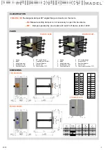
CLASSIFICATION

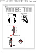
PARTS

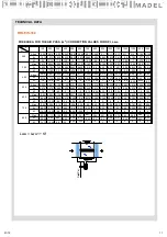
DIMENSIONS

6.

Brida de conexión  a 90º

7.

Mecanismo  /MA/

8.

Indicador  de posición

9.

Pulsador  de accionamiento

10. Fusible térmico a 72ºC

FOK-EIS-180-MA

FOK-EIS-180-MF

3

01/19

L

200
250
300
350
400
450

500
550
600

700
800

200
250
300
350
400
450

500
550
600
700
800

(mm)

H

(mm)

H1

(mm)

-
-
-
-
-

25

50
75

100
150

200

900

1000
1100
1200
1300
1400
1500

L

(mm)

FOK-EIS-180 /CR 

FOK-EIS-180-MA

5

7

9

10

8

2

4

6

1

3

8

2

4

6

1

3

5

7

9

10

FOK-EIS-180-MF

Ref.

A

(mm)

B

(mm)

C

(mm)

MFS…

115

121

32

MFS…

115

121

32

MFS…

191

121

40

MFB…

150

121

25

MFB…

160

121

32

S/ dim.

FOK-EIS-180

Rectangular damper 90º angled flange connection to the ducts.

…-MA

Manual resetting damper. Is not necessary to open the box device.

…-MF…

Damper operated by an actuator with switch off device at 24 or 230V.

1.

Casing

2.

Blade

3.

Airtightness  seal

4.

Intumescent  seal

5.

Perimetral  frame

6.

90º angled  flange

7.

Operating  device  /MA/

8.

Position indicator

9.

Test button

10. Thermal fuse  72ºC

1.

Casing

2.

Blade

3.

Airtightness  seal

4.

Intumescent  seal

5.

Perimetral  frame

6.

90º angled  flange

7.

Actuator  /MF

…/

8.

Position indicator

9.

Test switch

10. Thermoelectrical  fuse  72ºC

Summary of Contents for FOK-EIS-180-MF Series

Page 1: ...the structural elements of compartmentalisation which limits the risk of spreading of fire by interior of the building FOK EIS 180 fire dampers are according with the following standards The casing is...

Page 2: ...mm Built in 0 180 EI 180 ve i o S 500Pa Rigid floor Hormig n armado 200 mm Built in 0 360 EI 180 ve i o S 300Pa Sensing element load bearing capacity Sensing element response temperature Closure time...

Page 3: ...B mm C mm MFS 115 121 32 MFS 115 121 32 MFS 191 121 40 MFB 150 121 25 MFB 160 121 32 S dim FOK EIS 180 Rectangular damper 90 angled flange connection to the ducts MA Manual resetting damper Is not ne...

Page 4: ...pen resetting Manual Turning counterclockwise 90 the manual resetting axe using a tool with a smaller diameter than 8mm C Automatic Electrical connection Switches normally closed contacts COM NF NO CO...

Page 5: ...esetting Automatic closing by fuse 72 C Remote closing by interruption of power supply Manual test switch LED status fusible indicator Position damper indicator Closed switches IP54 Protection 72 C A...

Page 6: ...h allen key D To keep the blade open lock by manual lock Automatic By supplying the power supply E Electrical connection Fixed switching points at 5 and 80 Fixed switching point at 5 to contact A Fixe...

Page 7: ...tallation regarding this document the fire damper will not comply the classification Install the fire damper with the blade closed and avoid excessive pressures in its casing Avoid to project material...

Page 8: ...supporting construction sealing Dimensions Supporting construction Sealing Classification 200 x 200 to 1000 x 600 Rigid wall Brick wall 110mm Mortar EI180 ve i o S 300Pa 200 x 200 to 1000 x 600 Rigid...

Page 9: ...ETAIL A 144 144 1 Operating device position 2 Support construction opening Hnominal 150 20 Lnominal 150 20 Starting plane of supporting construction sealing Dimensions Supporting construction Sealing...

Page 10: ...amper classed EIS 180 in accordance to the European Standard EN 13501 3 and certified CE according to EN 15650 series FOK EIS 180 MFS230V dim 500 x 300 Operated by means of a motorized operating devic...

Page 11: ...615 0 209 6 0 525 5 1 0 5 0 358 0 410 0 75 0 444 0 399 0 4 2 5 0 495 0 59 0 270 3 75 0 480 0 58 0 303 3 0 470 800 0 855 9 5 0 088 700 0 865 10 25 0 077 600 0 845 8 75 0 1 900 1000 0 830 8 0 111 Dpt P...

Page 12: ...3500 6500 8000 4 5 6 7 8 9 0 4 0 2 Kr 1 0 8 0 6 10 2 35 40 45 50 L wa1 dB A 1 1 5 3 4 2 Vf m s 1 5 2 3 4 5 6 7 8 9 10 0 15 0 02 DPt Pa 30 15 20 10 100 60 80 40 0 06 0 05 0 03 0 04 0 08 0 1 0 8 A free...

Reviews: