


2 ©2015
MadCow
Rocketry™
FG
Tomach™
Assembly
FG
Tomach™
Assembly
©2015
MadCow
Rocketry™
3
Please make sure you read all directions and understand how to assemble your model
before you start construction. It is also a good idea to test
fi
t each part before assembly.
Fiberglass parts still contain small amounts of mold release and other materials on the
surface that will inhibit adhesives and/or paint. It is important to clean each part prior
to assembly with a solution of 1 part rubbing alcohol, 3 parts water and a drop of dish
washing soap. IMPORTANT: do not sand any parts until after you have cleaned them -
you will embed the materials you are trying to clean making it dif
fi
cult to clean.
The G10 parts will have holding tabs left over from the CNC machine. These small tabs
will need to be sanded off before assembly. Before assembling any part with epoxy,
rough up the surface to be epoxied using course sandpaper. The scratches in the G10
surface will give the epoxy something to grab onto.
Step 6 – Balance and Nose Cone Assembly
Step 5 – Altimeter Bay Assembly
Refer to the Fiberglass Removable Altimeter Bay instructions and assemble.
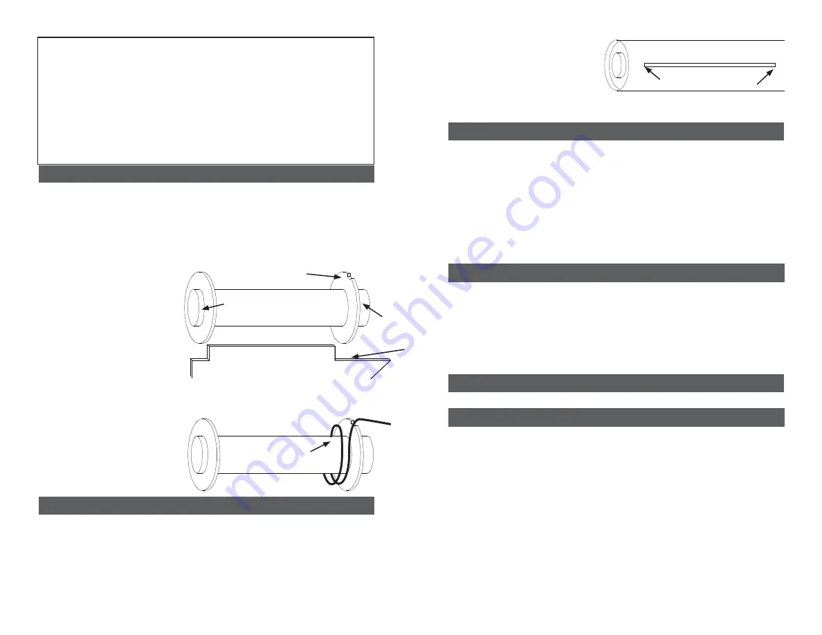
Step 1 – Motor Mount Assembly
Step 2 – Insert Motor Tube Assembly into Body Tube
Test
fi
t each of the
fi
ns into the pre cut
fi
n slots. Because G10 thickness varies, you will
need to sand the slot to the correct width. Wrap the shock chord into a small bundle
and stuff it inside the motor tube for this next step. Test
fi
t the motor tube assembly into
the body tube to ensure a snug
fi
t. Sand the centering rings if necessary. When you
are satis
fi
ed with the
fi
t, spread some epoxy on the inside of the body tube and slide the
forward centering ring of the motor assembly into the body tube.
Make sure you have
the motor assembly facing the right way!
Spread some more epoxy on the inside
edge of the body tube before sliding the rear centering ring into the body tube. Continue
Test
fi
t centering rings over the motor mount tube and sand motor tube if necessary. Also
test
fi
t the centering rings in the body tube and sand if necessary. Spread some epoxy on
the outside of one end of the motor tube and slide the ring (without the notch) until there
is approximately 1/2” of motor tube exposed. Make sure you clean the motor tube of any
epoxy so as not to interfere with the
fi
n tangs later. After the aft ring is dry, make a mark
1/2” from the other end of the motor tube. Spread some epoxy on the motor tube and
slide the forward ring until it aligns with the mark.
VERY IMPORTANT: make sure there
is not any epoxy on the motor tube that would interfere with the
fi
n tangs later on.
Fin
Fin Tang
1/2” Exposed
1/2” Exposed
Forward Ring Notch
Push cord in corner and
tack with epoxy
The shock cord in this kit consists
of a shorter section of Kevlar and a
longer section of nylon cording. The
two sections should be tied together
using a single overhand, ring bend
or double
fi
sherman’s knot. The
Kevlar section will be attached to
the motor mount and the nylon
section will be attached to the nose
cone.
Wrap the end of the Kevlar shock
cord around the forward end of the
motor tube and tack in place with
CA. Make sure the cord lays
fl
at
enough so it will not interfere with
the body tube when you slide the
motor tube inside. Apply some
epoxy to the cord to hold it in place.
Make sure the cord is secure
and will not come loose later with
ejection forces that will pull on the
shock cord.
Ensure rings are clear of the
fi
n slots
sliding the assembly inside the body tube
until the aft centering rings are just clear
of the
fi
n slots. It’s a good idea to test
fi
t
a
fi
n in each slot here before the epoxy
sets. Hold the body tube with the motor
tube assembly down until the epoxy sets.
Make sure the weight of the motor tube
doesn’t cause it to slide out of alignment.
Step 3 – Fin Assembly
Using a door jam or small section of angle stock, pencil a line halfway between two of
the
fi
ns that extends from the front to the back of the body tube. This line will be used
later to align the launch lugs. Test
fi
t each of the
fi
ns into the pre cut
fi
n slots. The
fi
n
should seat
fi
rmly against the motor tube - sand each
fi
n or slot if necessary. When you
are satis
fi
ed with the
fi
t, apply some epoxy to the end of the
fi
n tang that will contact the
motor tube. Also, spread a thin layer of epoxy on each side of the
fi
n tang. Slide the
fi
n
into place and check the alignment. Continue rechecking the
fi
n alignment until you are
sure the epoxy has set. Clean any excess epoxy from around the
fi
n joint. Repeat for
the remaining aft
fi
ns. Next, apply epoxy
fi
llets to both sides of each
fi
n by applying a
thin bead of epoxy at the
fi
n-body tube joing. Carefully smooth the epoxy
fi
llets with your
fi
nger before the epoxy sets. Allow each
fi
llet to set before rotating the airframe for the
next
fi
llet.
Step 4 – Launch Lug
Mark the CP point along the launch lug line you made in the previous step. Make sure
you measure the CP point from the tip of the nose cone and NOT the end of the body
tube. Apply a small amount of epoxy on the launch lug line about ¾” long on the CP
mark. Press one of the launch lugs into the epoxy and ensure that it is aligned with the
launch lug line previously drawn on the body tube. You can site down the tube and look
through the launch lug to make sure it is straight. Similarly epoxy the second launch
lug about 2” from the aft end of the body tube (aligned with the aft end of the
fi
ns). Site
down both launch lugs and make sure they are both aligned. If you have a ¼” launch
rod, you can use this to ensure that both lugs are aligned properly.
Epoxy the shorter coupler into the nose cone. Insert the nose cone and coupler into the
forward body tube to make sure the coupler is aligned properly. BE CAREFUL not to glue
the nose cone to the body tube. Mount
the
remaining
eyebolt
using
the
nut
and
washer
in
the
nose
cone
bulkplate.
Apply
some
epoxy
to
the
nut
so
it
will
not
come
loose
later.
Test
fit
the
bulkplate
in
the
base
of
the
nose
cone
and
sand
if
necessary,
but
don’t
glue
it
in
yet.
At
this
point,
pack
the
chute
and
assemble
the
rocket.
Assemble
your
model
and
insert
the
largest
motor
you
intend
to
fly
(or
simulate
the
weight
with
a
substitute)
and
ensure
that
the
CG
is
at
least
1
body
diameter
in
front
of
the
estimated
CP
point
specified
on
the
first
page.
The
CP
point
is
measured
from
the
tip
of
the
nose
cone.
If
the
CG
is
behind
the
desired
point,
add
weight
inside
the
nose
cone
by
pouring
lead
shot
into
the
nose
cone
tip
and
adding
some
epoxy.
When
you
are
satisified
with
the
balance
of
the
rocket,
epoxy
the
bulkplate
into
the
base
of
the
nose
cone
leaving
at
least
a
1/4”
lip
to
apply
a
fillet.
Next,
apply
a
fillet
of
epoxy
around
the
bulkplate
and
nose
cone
shoulder
joint.


