4
Controllers, Coils and Things
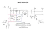
The 5v tap connects to the micro-controller (IC3: PIC12F509) for power. The relay coil (TQ2-L-5v) connects to pins 3 and
6 on the PIC. Pin4 of the PIC connects to ground via a 1k resistor and momentary switch. When the momentary switch is
depressed, the PIC “reads” that input and sends a voltage pulse to the relay to activate the coil. This causes the internal
DPDT of the relay to flip states (between bypass and effect in our case).
A couple other things happen at the same time when the switching engages.
Pin7 of the PIC is 0v in effect mode, 5v in bypass mode.
1) When the relay is in bypass-mode, pin7 of the PIC puts out a continuous 5v which is applied to the gate of Q1.
This grounds the power rail created by R6 to turn off the bypass LED by using the mosfet as a switch. IOW, the
nominal state for the LED is
on
and the mosfet “interrupts” (grounds) the power to the LED on bypass. The 20k
trimmer is for the user to control their preferred LED brightness.
2) Q2 is used as a variable resistor. In effect-mode, pin7 grounds the gate of Q2 and the resistance between the
drain and source is on the order of 120 Ohm. This acts as a small series resistance for the audio output and R7
behaves as output pull-down. From there, the audio output goes to the output jack.
3) In bypass mode, pin7 switches to 5v and the resistance between drain and source on Q2 goes to its nominal
value (infinite for argument’s sake). This mutes the PCB_OUT signal as the DPDT switches back to bypass-mode
to prevent any noise from going to the output jack. When it goes back to effect mode, the 100k resistor (R5)
grounds and the 100n cap begins to discharge. The slower discharge from the 100k/100n time constant may help
create more consistent on/off action in the momentary mode (my guess).
Note
- The schematic lists TQ2-L-5v as the relay in this schematic, but VFE used the TQ2-L-4.5v as well. According to
Peter both work fine but he tended to use the 4.5v relay. The 5v is listed in the Mouser BOM because it is more
regularly stocked.
- The J175 is a P-channel JFET, but is drawn here as an N-Channel. P-Channel must be used here for correct
operation.


