background image

Shopping List

QTY

Value

Type

Rating Spacing

2

100R

*see notes

1/4W

5mm

5

220R

Metal / Carbon Film

1/4W

7.5mm

5

1k43

Metal / Carbon Film

1/4W

7.5mm

1

22k

Metal / Carbon Film

1/4W

7.5mm

2

470k

Metal / Carbon Film

1/4W

7.5mm

3

1M

Metal / Carbon Film

1/4W

7.5mm

1

22pF

MLCC

25v min.

2.5mm

6

100n

MLCC

25v min.

2.5mm

2

47n

Film

25v min.

5mm

2

100n

Film

25v min.

5mm

3

220n

Film

25v min.

5mm

1

1uF

Film

25v min.

5mm

2

22uF

Electrolytic

25v min.

3

OPA2134a

or, other Dual Op-Amp

2

DPDT

On/On, Pin Mount

1

2k

Bourns 3362p

1

1kB

PCB Plastic Shaft

9mm

1

50kA

PCB Right Angle

16mm

2

10kA

PCB Dual Gang

16mm

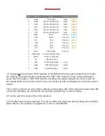
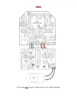
1) I suggest not using the two 100R resistors on the BOM and doing jumpers instead. Don’t be like 

me: building this project blindly and sticking two 100R 1/8W resistors in there without thinking be-

cause they fit the space. 100R 1/8W resistors will drop your supply voltages like a tank in jello. At 

the roughly 60mA current draw on the Focus, you will end up with a whopping 2.2v drop across each 

resistor. 

This could be improved by using higher wattage resistors there (like 1/4W) and lower values (like 10R 

or 22R) but ultimately, the circuit does not need the extra filtering or current limiting.

2) You can use 1k5 in place of the 1k43 resistors!

3) The OPA2134a is really expensive. You can try other, less expensive dual op-amps here. Anything 

that is rated for 18v operation. Suggestions: TL072 or JRC4580DD.

Summary of Contents for VFE Focus

Page 1: ...r guitar and amplifier without being stuck with the fixed filters of their usual boost pedal I approached Peter at VFE and he understood what I was after straight away the Focus was born very soon afterwards TIGHT Sets the frequency roll off point of the variable bass cut Turn counterclockwise to cut bass frequencies for a tighter bottom end RANGE 70Hz to 1 5kHz SMOOTH Sets the frequency roll off ...

Page 2: ...Note Use the values listed on the image above not the values indicated on the silk screen of the PCB Some values changed over time in the VFE product cycles Build Guide Dimensions 2 17 W x 2 025 H ...

Page 3: ...Trace Routing Knob Layout ...

Page 4: ...est not using the two 100R resistors on the BOM and doing jumpers instead Don t be like me building this project blindly and sticking two 100R 1 8W resistors in there without thinking be cause they fit the space 100R 1 8W resistors will drop your supply voltages like a tank in jello At the roughly 60mA current draw on the Focus you will end up with a whopping 2 2v drop across each resistor This co...

Page 5: ... mouser com Search ProductDetail aspx R OPA2134PAvirtualkey 59500000virtualkey595 OPA2134PA http www smallbear electronics mybigcommerce com ic opa2604ap DPDT On On Pin Mount http www smallbear electronics mybigcommerce com dpdt on on short lever pc mount 9mm Plastic Shaft 1kB http smallbear electronics mybigcommerce com alpha single gang 9mm right angle pc mount w knurled plastic shaft 16mm PCB M...

Page 6: ...e shown on the Trace layout on pg 2 has this resistor on the PCB PS Insofar as I can tell there is not real difference in v1 1 1 2 or 1 3 of the PCB other than this 1M resistor He may have done small tweaks on the trace routing or values but the values listed in the BOM are for the last version which is 1 3 All voltages on the ICs should read about 0v DC except pins 8 and 4 Pin8 all 7 86v Pin4 all...

Page 7: ...Wiring This project does require a charge pump on the Switching Board ...

Page 8: ...Schematic ...

Page 9: ...en before adding the 1M jumper across the DPDT right under the Focus v1 1 text Also the 100R resistors are on the PCB because I elected to short them on the bottom rather than remove them to lessen the chance of damaging it ...

Reviews: