background image

Notes

AquaboyDLX_2019

madbeanpedals

Calibration

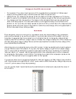
Before starting, remove IC4. This is necessary to start the biasing process. Set the controls as shown.

•  DELAY, MIX controls to their center position.

•  FDBK at about 1/3 up.

•  RATE and DEPTH controls all the way down.

•  MOD switch to the center (off) position.

•  BIAS1, BIAS2 and Cancel trimpots to their center position.

•  T1 full CCW.

•  If you have frequency measurement on your DMM, adjust the Clock trimmer to about 6.5kHz while 

probing either pin2 or pin4 of IC5. If you don’t have this feature set the Clock trim half-way up.

1. 

Audio probe pin7 of IC3 to confirm you have signal reaching the BBD. It is normal for this signla to 

be loud and even somewhat distorted. You may hear clock noise, as well. If you have no signal at 

pin7 you need to work your way back through the circuit to find out what went wrong (start at pin7 

of IC2).

2.  Audio probe pin3 or 4 of IC3 while either strumming the guitar or send some audio through the 

input of the effect (a looper, etc). Adjust the BIAS1 trimmer until you get delay passing. The area 

over which the trimmer will result in delay is usually about 1/4 of its range. Continue refining the 

position of BIAS1 until you get the lowest amount of distortion on the delay signal. 

3. 

Now probe pin4 of IC3 to confirm it is also passing delay. If it does not, make sure that you have 

clock frequency on both pins 2 and 6.

4.  Unplug power and replace IC4. Repeat the same procedure above by audio probing pin3 of IC4 

and adjusting BIAS2 for the lowest amount of distortion on the repeats. Confirm that pin4 is also 

passing delay.

5. 

Set the Delay pot to Max. Now finely adjust the CLOCK trimmer until just before you hear any high 

pitch whine in the audio path. This is the maximum delay setting. The clock frequency should land 

somewhere around mid-6kHz. Leave the Cancel trim in the center position. 

6.  T1 fully CCW is the lowest volume/# of repeats you can get with FDBK fully up. At about 3/4 up, 

T1 is the stock setting of the DM-2. I suggest setting FDBK about 90% of the way up and then 

adjust T1 until it just starts to go into self-oscillation. That should give you plenty of repeats on the 

control with the possibility of going into oscillation if that’s your thing.

If you do have a scope, you can use it instead of an audio probe to make the proper adjustments to 

BIAS1, BIAS2, Clock and the Cancel trimpots. When using a scope, set the Cancel trimpot so that the 

two output waveforms from pins 3 and 4 of IC4 converge.

Summary of Contents for Aquaboy Deluxe 2019

Page 1: ...udio probe and some kind of testing rig breadboard set up to get the ABDX properly set up Controls DELAY The total amount of signal delay from slapback to approximately 500ms FDBK The number and intensity of delay repeats from one to infinity self oscillation MIX The level of delay signal relative to the dry path of the guitar signal RATE The speed of the delay modulation from slowest to very fast...

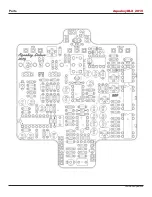
Page 2: ...Parts AquaboyDLX_2019 madbeanpedals ...

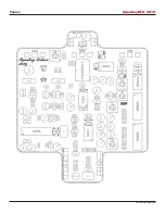
Page 3: ...Values AquaboyDLX_2019 madbeanpedals ...

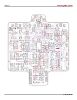
Page 4: ...Traces AquaboyDLX_2019 madbeanpedals ...

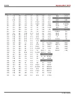
Page 5: ...2 220n C43 10uF T1 50k R13 100k R44 220k C13 100pF C44 47uF CLOCK 1M R14 100k R45 220k C14 10uF Diodes Pots R15 10k R46 1k C15 6n8 D1 15v Zener RATE 100kC R16 10k R47 4k7 C16 100n D2 1N5817 DEPTH 50kB R17 10k R48 4k7 C17 330pF D3 1N5817 MIX 50kB R18 10k R49 4k7 C18 10uF BP D4 1n914 FDBK 50kB R19 10k R50 4k7 C19 1uF LED1 2 any DELAY 1MB R20 10k R51 220k C20 10uF BP LED3 4 RED R21 4k7 R52 33k C21 1u...

Page 6: ...Carbon Film 1 8W LED 2 Red Diffused 3 or 5mm 47k 5 Metal Carbon Film 1 8W MPSA18 4 82k 1 Metal Carbon Film 1 8W BS250p 1 100k 8 Metal Carbon Film 1 8W TL072 1 220k 3 Metal Carbon Film 1 8W NE570 1 470k 3 Metal Carbon Film 1 8W MN3005 2 1M 2 Metal Carbon Film 1 8W MN3101 1 2M2 1 Metal Carbon Film 1 8W TL062 1 100pF 5 Ceramic MLCC 25v min LT1054 1 330pF 2 Ceramic MLCC 25v min L7815 1 15v regulator T...

Page 7: ...252BSNc10CtLc4Cw 3D L7815 https www mouser com ProductDetail STMicroelectronics L78L15ACZ qs sGAEpiMZZMtUqDgmOWBjgLAmId5B 2FjmHe8yhWKd8M1Y 3D 9203 http smallbear electronics mybigcommerce com photocells cds 5mm diameter DPDT On Off On http smallbear electronics mybigcommerce com dpdt center off pc mount Bourns 3362p 10k 25k 50k 1M https www mouser com ProductDetail Bourns 3362P 1 103LF qs sGAEpiMZ...

Page 8: ...he lower the clock frequency the more delay you get but the further it creeps into the audio range Analog delays attempt to optimize the balance between signal degradation and clock bleed by a series of additional signal processing chains These are compression filtering and expansion The compressor portion beefs up the incoming signal to minimize its degradation while traversing the BBD The filter...

Page 9: ...he ABDX you may remember I suggested that if you wanted to run it at higher than 9v to change the voltage divider resistors here R15 and R16 to a larger value to increase the voltage output pin7 of the compressor the idea being that a larger voltage there would increase headroom and also the bias voltage of the pre emphasis filter that follows After doing some more listening tests on the 2019 vers...

Page 10: ...ontinue refining the position of BIAS1 until you get the lowest amount of distortion on the delay signal 3 Now probe pin4 of IC3 to confirm it is also passing delay If it does not make sure that you have clock frequency on both pins 2 and 6 4 Unplug power and replace IC4 Repeat the same procedure above by audio probing pin3 of IC4 and adjusting BIAS2 for the lowest amount of distortion on the repe...

Page 11: ...Wiring Diagram AquaboyDLX_2019 madbeanpedals The LED indicators for the two bypass switches as well as LED4 modulation rate indicator should be soldered directly to the PCB ...

Page 12: ...cks switches and pots you use madbeanpedals A 125BB enclosure is the same foot print but taller than the 1590BB shown here If you like more room to work with use this template with the 125BB and just move the top jacks up accordingly It gives you the advantage of moving the input jack further away from the delay clock too ...

Page 13: ...2 NE570 IC4 MN3005 IC7 LT1054 D 9 42 1 1 08 1 17 88 1 1 63 G ignore 2 1 77 2 7 12 2 5 S 9 26 3 1 77 3 5 88 3 0 REG L7815 4 0 4 5 85 4 0 I 17 55 5 1 77 5 0 5 0 G 0 6 1 77 6 7 12 6 2 54 O 14 97 7 2 98 7 6 19 7 1 39 8 1 77 8 0 96 8 9 26 9 1 77 IC5 MN3101 Q1 MPSA18 10 3 98 1 14 24 C 17 97 11 3 99 2 7 12 B 6 9 12 1 77 3 0 E 6 6 13 14 97 4 7 12 Q2 MPSA18 14 1 77 5 6 64 C 14 97 15 1 77 6 7 35 B 2 97 16 0...

Page 14: ...a to put some heat shrink or other light blocking material over your LED LDR combo At least while testing it before boxing Tip Use an MLCC or Mica 100pF for C37 and a Delay pot that measures as close to 1M as possible These will give you the best delay time ...

Page 15: ...Schematic AquaboyDLX_2019 madbeanpedals ...

Reviews: