background image


Macurco RD-xx User Manual 

REV – 2.1 

[34-2900-0511-7 ] 

26 

|


P a g e


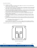
Figure 7-1 Calibration Connection 

4.


Turn on the regulator to start the gas flow and wait with the gas applied continuously. 

5.


 When the gas concentration reaches 1000ppm the display will flash back and forth between “FAn” and ALr (if both 

Alarm Relay and Fan Relay are activated). Note: If the Fan relay does not change state within 5 minutes, there are four 

possibilities: 

a.


The gas cylinder is empty, check the pressure gauge. Replace the gas cylinder if 25psi or less. 

b.


The detector has fan relay delay set to 3 or more minutes. Set fan relay to 0 minutes and repeat the test. 

c.


The detector needs field calibration or servicing (return unit to the factory for servicing). 

6.


Remove the gas from the sensor. Proceed to Test the Alarm relay or replace the top cover. Fan relay test is complete. 

7.4.3


Testing the Alarm Relay 

1.


Connect the 1200ppm cylinder of Refrigerant to the regulator. 

2.


Check the pressure gauge. If there is 25psi or less the cylinder should be replaced. 

3.


Place the test hood over the gas sensor. Turn on the regulator to start the gas flow. 

4.


Fan relay should activate according to the Fan Relay delay settings. 

5.


When the gas concentration reaches the Alarm Relay setting, (i.e. 1000ppm) the display will flash “ALr”. The buzzer will 

sound indicating “Alarm” if the buzzer is turned “On”.  

Note: If the Alarm relay fails to operate within 5 minutes, there are three possibilities: 

a.


The gas cylinder is empty, check the pressure gauge. Replace the gas cylinder if 25-psi or less. 

b.


The detector needs field calibration or servicing (return unit to the factory for servicing).   

6.


Remove the gas from the sensor after Test. Proceed to Test the 4-20mA output or replace the top cover. Alarm relay 

test is complete. 

7.4.4


Testing the 4-20mA loop 

1.


Connect the 1200ppm cylinder of Refrigerant to the regulator. 

2.


Check the pressure gauge. If there is 25-psi or less the cylinder should be replaced. 

3.


Place the test hood from the regulator over the gas sensor. Turn on the regulator to start the gas flow. 

4.


The Fan relay should activate according to the Fan Relay Delay settings. 

5.


The Alarm relay should activate if reading is above 1000ppm. 

6.


The 4-20 mA output should output 4mA in clean air and 20mA when in Alarm.  

Note: If the 4-20mA output does not change within 5 minutes, there are three possibilities: 

a.


The gas cylinder is empty, check the pressure gauge. Replace the gas cylinder if 25-psi or less. 

b.


The detector has 4-20 mA option set to “OFF”. Set 4-20mA option to “bAS or EnH” and repeat the test.  

c.


The detector needs field calibration or servicing (return unit to the factory for servicing). 

7.


Remove the gas from the sensor. Re-assemble the RD-xx (make sure the LED is aligned with the front case hole). 4-20 

current loop test is complete. 

7.5


Field Calibration Procedure 

Note:

 For optimum calibration results, the unit should be in clean air, in a low ambient air flow and have uninterrupted power 

for 7 days. 

RD-xx has “CAL” top level menu that can be used to perform field calibration. ‘tSC’, ‘Spn’ and ‘End’ are sub-menu within “CAL” 

menu. ‘tSC’ is read only menu and represents the time since last calibration. If you enter this sub-menu, it will display value in 

format Y.MM. “MM” are for months and “Y” for year. E.g. if the value is 0.05 then it has been 5 months since the unit was last 

calibrated. ‘Spn’ sub-menu is used during field calibration procedure as described in following procedure. ‘End’ sub-menu is 

used to exit out of ‘CAL’ menu. 


Summary of Contents for RD-12

Page 1: ...IMPORTANT Keep these user instructions for reference Macurco RD 6 RD 12 Refrigerant Detector Controller and Transducer User Instructions ...

Page 2: ...8 4 4 Default Factory Settings 18 4 4 1 Selecting Default Configuration dEF 19 4 4 2 Power Up Test Setting PUt 19 4 4 3 Buzzer Setting bUZ 19 4 4 4 Alarm Relay Configuration Arc 19 4 4 5 Fan Relay Delay Setting Frd 19 4 4 6 Fan Relay Minimum Runtime Setting Frr 19 4 4 7 Fan Relay Latching Setting FrL 19 4 4 8 Trouble Fan Setting tFS 20 4 4 9 4 20mA Output setting 420 20 4 5 13 Calibration Period S...

Page 3: ...the Fan Relay 25 7 4 3 Testing the Alarm Relay 26 7 4 4 Testing the 4 20mA loop 26 7 5 Field Calibration Procedure 26 8 Appendix A Table of Figures 28 9 Macurco Gas Detection Product limited warranty 29 Technical Support Contact Information 29 General Contact Information 29 ...

Page 4: ...els of the gas being monitored may be present and could result in overexposure and cause serious injury or death For proper use see supervisor or User manual or contact Technical Support at 1 844 325 3050 High voltage terminals 120 240 VAC are located within this detector presenting a hazard to service technicians Only qualified technicians should open the detector case and service the internal ci...

Page 5: ...and flammability See ANSI ASHRAE Standard 34 2007 Designation and Safety Classification of Refrigerants for details Always review the refrigerant MSDS and safety classifications before use RD xx can be used stand alone with the Macurco Detection and Ventilation Control Panel other 12 VAC or 24 VDC fire security panels or building automation systems WARNING Use only for monitoring the gas which the...

Page 6: ...Color White or Dark grey Connections plugs terminals Mounting box not included 4x4 electric Fan relay 5 A 240 VAC pilot duty SPDT latching or non latching Fan Delay Settings of 0 1 3 default 5 and 10 minutes Fan Relay Minimum Runtime settings are 0 default 3 5 10 or 15 minutes Fan relay latching or not latching default selectable Alarm relay 0 5A 120 V 60 VA Alarm relay actuation selectable N O de...

Page 7: ...d open the detector case and service the internal circuits Ensure power is de energized from the detector relays prior to servicing the unit Failure to do so may result in electrical shock 3 2 Installation 3 2 1 6 Series Low Voltage 1 The RD 6 mounts on a 4 square or 4x4 electrical box supplied by the contractor Do not mount the RD 6 inside another box unless it has good air flow through it 2 Conn...

Page 8: ... disengage once both of these conditions have been met Refrigerant gas concentration has dropped below 1000ppm Fan Relay Runtime has been exceeded The fan relay will engage in trouble fault condition if the Trouble Fan Setting Option is set to On and will disengage once trouble fault condition is cleared 10 The Current Loop is 4 mA in normal condition and 20 mA when in alarm Figure 3 2 6 Series Re...

Page 9: ...one foot above the floor 3 See application building code for fan size and air changes per period of time 4 Make sure that there are air inlets to provide adequate airflow throughout the building 5 The RD xx fan relays are dry contact and can switch up to 240V see section 2 4 Specifications 6 Several fan relays starters may be used Match the relays to the fan specifications ...

Page 10: ...ovides battery backup power to the RD 6 3 The RD 6 dry contact relay can use panel power or fan power See Ratings 4 Match fan relay contacts to fan size and coil voltage to a power source 5 Alarm control panels are available with many features and can control other devices such as smoke detectors fire detectors and burglar alarms Figure 3 6 6 Series DVP 120 Control Panel Diagram ...

Page 11: ...DT Form C are for pilot duty only capable of switching 10 amps loads up to 240VAC Note Transducer power connections are non polarized Figure 3 7 6 Series Alternate Alarm Panel In this application above the Fan or primary relay is used as a low level alarm relay The Alarm or secondary relay is used as a supervisory relay when utilized in the normally closed configuration The RD 6 monitors all criti...

Page 12: ...rminals The common COM normally open N O and the normally closed N C contact The fan relay can switch up to 5 0 A up to 240 VAC See OPERATION section of these User Instructions for details on relay settings 5 The Fan Relay can be configured for latching or non latching default when activated when the gas concentration exceeds1000ppm Once latched in power will need to be interrupted or the TEST but...

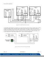
Page 13: ...Macurco RD xx User Manual REV 2 1 34 2900 0511 7 13 P a g e Figure 3 11 12 Series Stand Alone Layout Figure 3 12 12 Series Multiple Device Diagram ...

Page 14: ...Macurco RD xx User Manual REV 2 1 34 2900 0511 7 14 P a g e Figure 3 13 12 Series Alarm Control Panel Diagram Figure 3 14 12 Series DVP 120 Control Panel Diagram ...

Page 15: ...mally closed configuration The RD 12 monitors all critical functions of the unit through software diagnostics that continually test and verify its operations If a problem is found the unit will switch to a fail safe error mode or trouble condition In this error mode the Fan and Alarm relays will be activated indicating the trouble condition at panel and the RD 12 display will flash the error See t...

Page 16: ...Connection The external alarm connections A and B are available at the Alarm modular connector There is no polarity for these connections To install the wiring for the alarm contacts disconnect the connector from the header on the detector Strip the insulation of each wire back approximately 1 4 in 6 5 mm insert the bare wire into the terminal and tighten the screw clamp Ensure that the wire canno...

Page 17: ...trip the insulation of each wire back approximately 1 4 in 6 5 mm insert the bare wire into the terminal and tighten the screw clamp Ensure that the wire cannot easily be pulled from the connector When the wires are connected seat the modular connector into the header ensuring that the latch engages Note The 4 20mA current loop outputs may be used with the Macurco DVP 120 control panel or other sy...

Page 18: ...N Clean Air With the 4 20 mA function turned On and the current gas concentration below 1000ppm the 4 20mA loop will output 4 mA Alarm With the 4 20 mA function turned On 4 20mA will output 20mA when unit goes into Alarm Trouble With the 4 20 mA function turned On and Trouble Fan Setting enabled The 4 20mA loop will output 1 mA or 24 mA depending on the Trouble condition See Section 5 1 On Board D...

Page 19: ...Configuration in normal mode push the Next button to get to Con or the Configuration menu Then push the Enter button to enter the Con menu The fourth selection is the Arc or Alarm Relay Configuration Push Next three times to get to Arc then Enter If the relay is nO normally open push Next to turn it to nC flashing then push Enter to confirm the change solid and push Enter again to return to Arc in...

Page 20: ...sh Enter to confirm the change solid and push Enter again to return to 420 in the Con menu Push Next until End is displayed then push Enter to get back to normal operation NOTE RD xx will transmit information about calibration period to Macurco Control Panel via 4 20 mA output only when 4 20mA output setting is set to EnH 4 5 13 Calibration Period Settings CAL Value selected in Calibration Period ...

Page 21: ...r troubleshooting 0 mA is most likely a connection problem 1 mA indicates Calibration Overdue if 4 20mA is configured to EnH 20 mA is alarm condition 24 mA indicates a Trouble condition 5 1 2 t Error Codes Error Codes tXX t01 Sensor Fatal Error Sensor missing t02 Temperature compensation failure t04 EEPROM bad checksum t08 Sensor is shorted t10 Bad EEPROM t20 Bad calibration t40 Factory calibratio...

Page 22: ...5 3 End of Life Signal The RD xx has a long life non replaceable solid state sensor Seven 7 years after the RD xx is installed the sensor end of life signal will be activated indicating that the RD xx has reached the end of its typical usable life The end of life signal will cause an error code t200 Sensor expired See Error Codes section The end of life signal can be silenced for 48 hours by press...

Page 23: ...g All RD xx units are factory calibrated and 100 tested for proper operation During normal operation the green status indicator LED light will be on steady the fan alarm relay will be in standby mode and the 4 20 mA output will be at 4mA in clean air The unit also performs a regular automatic self test during normal operation If the unit detects an improper voltage or inoperable component it will ...

Page 24: ... output and the sensor response to gas From normal operation mode press the Next button 2 times to get to the Test Mode tSt Press the Enter button once to get into the Test Menu Press the Next button to scroll through the five test options and press Enter to initiate the selected test Note that if the relay or 4 20 mA output has been disabled the test selection will not be displayed in the test me...

Page 25: ...be tested do not use until the reason can be determined and corrected Do not cover or obstruct display or visual alarm cover Ensure sensor inlets are unobstructed and free of debris 7 4 Gas Testing It is recommended to perform gas test for RD xx units at least once every 3 months 7 4 1 Assembling the Regulator Hose and Test hood 1 Open the FCK Connect the 1200ppm gas cylinder to the regulator 2 Co...

Page 26: ...emove the gas from the sensor after Test Proceed to Test the 4 20mA output or replace the top cover Alarm relay test is complete 7 4 4 Testing the 4 20mA loop 1 Connect the 1200ppm cylinder of Refrigerant to the regulator 2 Check the pressure gauge If there is 25 psi or less the cylinder should be replaced 3 Place the test hood from the regulator over the gas sensor Turn on the regulator to start ...

Page 27: ...ond 6 Turn the regulator on opening fully to start the flow of gas to the RD xx sensor 7 When the countdown of 120 alternating with GAS is complete the unit will go into Span During span the display will alternate between SPn and countdown from 240 The countdown is decremented every second Once the countdown of 240 is complete then the field calibration is complete it will display the result of th...

Page 28: ...Diagram 10 Figure 3 7 6 Series Alternate Alarm Panel 11 Figure 3 8 6 Series Horn Strobe Combo Wiring 11 Figure 3 10 12 Series Rear View 12 Figure 3 11 12 Series Stand Alone Layout 13 Figure 3 12 12 Series Multiple Device Diagram 13 Figure 3 13 12 Series Alarm Control Panel Diagram 14 Figure 3 14 12 Series DVP 120 Control Panel Diagram 14 Figure 3 15 12 Series Alternate Alarm Panel 15 Figure 3 16 1...

Page 29: ... IMPLIED WARRANTIES OF MERCHANTABILITY AND FITNESS FOR PARTICULAR PURPOSE ARE LIMITED TO A PERIOD OF TWO 2 YEARS FROM THE PURCHASE DATE Macurco shall not be liable for any incidental or consequential damages for breach of this or any other warranty express or implied arising out of or related to the use of said gas detector The manufacturer or its agent s liability shall be limited to replacement ...

Page 30: ......

Page 31: ...IMPORTANT Conservez ces instructions d utilisateur pour référence Macurco RD 6 RD 12 Détecteur de réfrigérant contrôleur et transducteur Instructions de l utilisateur ...

Page 32: ...0mA 19 4 4 Paramètres par défaut Paramètres d usine 19 4 4 1 Sélection de configuration par défaut DEF 20 4 4 2 Réglage de test power up U 20 4 4 3 Réglage buzzer buz 20 4 4 4 Configuration du relais d alarme arc 21 4 4 5 Réglage de retard de relais de ventilateur r 21 4 4 6 Fan Relay Minimum Runtime Setting Frr 21 4 4 7 Réglage de verrouillage du relais de ventilateur frl 21 4 4 8 Trouble Fan Set...

Page 33: ...eurs 27 7 4 3 Test du relais d alarme 28 7 4 4 Test de la boucle 4 20mA 28 7 5 Procédure d étalonnage sur le terrain 29 8 Annexe A Tableau des chiffres 30 9 Garantie limitée du produit de détection de gaz Macurco 31 Coordonnées du support technique 31 Informations générales sur les contacts 31 ...

Page 34: ...ie que des niveaux plus élevés de gaz surveillés peuvent être présents et pourraient entraîner une surexposition et causer des blessures graves ou la mort Pour une utilisation appropriée consultez le superviseur ou le manuel d utilisation ou communiquez avec le support technique au 1 844 325 3050 Des bornes à haute tension 120 240 VAC sont situées à l intérieur de ce détecteur ce qui présente un d...

Page 35: ...es divisés en deux groupes en fonction de la toxicité et de l inflammabilité Voir ANSI ASHRAE Standard 34 2007 Classification de désignation et de sécurité des réfrigérants pour plus de détails Examinez toujours les MSDS réfrigérants et les classifications de sécurité avant utilisation RD xx peut être utilisé seul avec le panneau de contrôle de détection et de ventilation Macurco 12 autres panneau...

Page 36: ... Connexions prises terminaux Boîte de montage non inclus 4x4 électrique Relais de ventilateur 5 A 240 VAC service de pilote SPDT verrouillage ou non verrouillage Paramètres de retard de ventilateur de 0 1 3 par défaut 5 et 10 minutes Les paramètres d exécution minimum du relais de ventilateur sont de 0 par défaut 3 5 10 ou 15 minutes Verrouillage du relais de ventilateur ou non verrouillage par dé...

Page 37: ...orsque la température ambiante normale est inférieure à 0 F ou dépasse 125 F en dessous de 18 C ou au dessus de 52 C Avertissement Des bornes à haute tension 120 240 VAC sont situées à l intérieur de ce détecteur ce qui présente un danger pour les techniciens de service Seuls les techniciens qualifiés doivent ouvrir le boîtier du détecteur et entretenir les circuits internes Assurez vous que la pu...

Page 38: ...mpue ou le bouton TEST appuyé pour désaqueter l état du relais Le relais de ventilateur s engagera si la concentration de réfrigérant est supérieure à 1000ppm pour plus longtemps que le temps de retard de relais de ventilateur À moins qu il ne soit configuré pour le verrouillage le relais du ventilateur se désengagera une fois que ces deux conditions auront été remplies La concentration de gaz réf...

Page 39: ...tez le code du bâtiment de l application pour la taille des ventilateurs et les changements d air par période de temps Assurez vous qu il y a des entrées d air pour fournir un débit d air adéquat dans tout le bâtiment Les relais de ventilateur RD xx sont à contact sec et peuvent passer jusqu à 240V voir la section 2 4 Spécifications Plusieurs relais de ventilateur démarreurs peuvent être utilisés ...

Page 40: ...c RD 6 peut utiliser la puissance du panneau ou la puissance du ventilateur voir évaluations Associez les contacts de relais de ventilateur à la taille du ventilateur et la tension de bobine à une source d alimentation Les panneaux de commande d alarme sont disponibles avec de nombreuses fonctionnalités et peuvent contrôler d autres dispositifs tels que les détecteurs de fumée les détecteurs d inc...

Page 41: ...n d alarme Ces relais SPDT Form C sont pour le service pilote seulement capable de commuter 10 ampères charges jusqu à 240VAC Remarque Les connexions de puissance transducteurs ne sont pas polarisées Figure 3 7 Panneau d alarme de remplacement de la série 6 Dans cette application ci dessus le ventilateur ou le relais principal est utilisé comme relais d alarme de bas niveau Le relais d alarme ou s...

Page 42: ...lement ouvert N O et le contact normalement fermé N C Le relais de ventilateur peut passer jusqu à 5 0 A jusqu à 240 VAC Voir la section OPERATION de ces instructions utilisateur pour plus de détails sur les paramètres du relais Le relais de ventilateur peut être configuré pour le verrouillage ou le non verrouillage par défaut lorsqu il est activé lorsque la concentration de gaz dépasse 1000ppm Un...

Page 43: ...Macurco RD xx User Manual REV 2 1 34 2900 0511 7 13 P a g e Figure 3 10 Vue arrière de la série 12 Figure 3 11 Mise en page autonome de la série 12 ...

Page 44: ...Macurco RD xx User Manual REV 2 1 34 2900 0511 7 14 P a g e Figure 3 12 Diagramme de périphériques multiples de la série 3 12 Figure 3 13 Diagramme du panneau de configuration d alarme de la série 3 13 ...

Page 45: ...a série 120 Figure 3 15 Panneau d alarme de rechange de la série 12 Dans cette application ci dessus le ventilateur ou le relais principal est utilisé comme relais d alarme de bas niveau Le relais d alarme ou secondaire est utilisé comme relais de surveillance lorsqu il est utilisé dans la configuration normalement fermée ...

Page 46: ...et vérifient continuellement ses opérations Si un problème est constaté l appareil passera à un mode de panne erreur ou à un problème Dans ce mode d erreur les relais Fan et Alarme seront activés indiquant l état de difficulté au panneau et l écran RD 12 clignotera l erreur Voir l option de réglage du ventilateur trouble Figure 3 16 12 Series Horn Strobe Combo Wiring ...

Page 47: ...assurez vous qu elle se verrouille correctement dans l en tête 3 3 1 3 Connexion relais d alarme Les connexions d alarme externe A et B sont disponibles sur le connecteur modulaire Alarm Il n y a pas de polarité pour ces connexions Pour installer le câblage des contacts d alarme déconnectez le connecteur de l en tête du détecteur Retirez l isolant de chaque fil d environ 1 4 po 6 5 mm insérez le f...

Page 48: ...eur de l en tête du détecteur Retirez l isolant de chaque fil d environ 1 4 po 6 5 mm insérez le fil nu dans le terminal et serrez la pince à vis Assurez vous que le fil ne peut pas être facilement tiré du connecteur Lorsque les fils sont connectés siège le connecteur modulaire dans l en tête assurant que le verrou s engage Remarque Les sorties de boucles actuelles 4 20mA peuvent être utilisées av...

Page 49: ...A sélectionnés pour bAS ou EnH sont considérés comme fonction 4 20mA activée Air pur Avec la fonction 4 20 mA activée et la concentration actuelle de gaz en dessous de 1000ppm la boucle 4 20mA sortira 4 mA Alarme Avec la fonction 4 20 mA tournée On 4 20mA sortira 20mA quand l unité entrera dans l alarme Problème Avec la fonction 4 20 mA activée Activé et le réglage du ventilateur trouble activé La...

Page 50: ... Réglage de test power up U Pour sélectionner la configuration de test power up en mode normal appuyez sur le bouton Suivant pour obtenir de Con ou le menu Configuration Appuyez ensuite sur le bouton Entrée pour entrer dans le menu Con Ensuite appuyez sur le bouton Suivant pour obtenir à la deuxième sélection PUt ou Power Up Test paramètre Push Enter Si le test est On appuyez sur Suivant pour l ac...

Page 51: ...z sur Entrer à nouveau pour revenir à Frr dans le menu Con Appuyez ensuite jusqu à ce que End s affiche puis poussez Entrée pour revenir à l opération normale 4 4 7 Réglage de verrouillage du relais de ventilateur frl Pour sélectionner l option de verrouillage du relais de ventilateur en mode normal appuyez sur le bouton Suivant pour obtenir de Con ou du menu Configuration Appuyez ensuite sur le b...

Page 52: ...étalonnage Les paramètres de la période d étalonnage ne peuvent pas être modifiés si RD xx indique étalonnage dû ou étalonnage en retard Pour sélectionner l option période d étalonnage en mode normal appuyez sur le bouton Suivant pour obtenir de Con ou du menu Configuration Appuyez ensuite sur le bouton Entrée pour entrer dans le menu Con La dixième sélection est le paramètre CAL ou Calibration Pe...

Page 53: ...obablement un problème de connexion 1 mA indique Calibration En retard si 4 20mA est configuré sur EnH 20 mA est l état d alarme 24 mA indique une condition de problème 5 1 2 Codes d erreur ErreurCodes tXX t01 Erreur fatale du capteur Capteur manquant t02 Échec de compensation de température t04 EEPROM mauvais checksum t08 Le capteur est court circuité t10 Bad EEPROM t20 Mauvais étalonnage t40 Déf...

Page 54: ...lle ou faible Ils nécessitent la présence d oxygène ambiant normal dans leur environnement de fonctionnement afin de fonctionner correctement Les caractéristiques du capteur peuvent être modifiées en raison du trempage ou de l éclaboussure du capteur avec de l eau Évitez les chocs mécaniques La rupture des fils de plomb peut se produire si le capteur est soumis à un choc 5 3 Signal de fin de vie L...

Page 55: ...férable à l aide d un chiffon humide avec un détergent doux ou du savon Utilisez un aspirateur à l aide d une brosse souple pour enlever la poussière ou la contamination sous le couvercle Ne pas souffler le capteur avec de l air comprimé Attention Évitez l utilisation de matériaux de nettoyage durs d abrasifs et d autres solvants organiques Ces matériaux peuvent rayer en permanence les surfaces et...

Page 56: ...ont câblés de la manière normale le ventilateur doit fonctionner o La sortie 4 20mA passera alors de 4 à 16 mA au cours des 130 prochaines secondes de l essai donc si le circuit est câblé de la manière normale le panneau de commande ou le système d automatisation du bâtiment devrait répondre o À la fin du cycle d essai la lumière deviendra verte et sera sur stable fonctionnement normal le ventilat...

Page 57: ...a bonne performance du moniteur Le défaut de le faire peut nuire à la performance du produit et entraîner une maladie ou un décès Lors d un essai de vérification d étalonnage essai de bosse n utilisez que du gaz d étalonnage certifié au niveau de concentration requis Ne pas tester avec du gaz d étalonnage expiré Si l instrument ne peut pas être testé ne pas utiliser jusqu à ce que la raison peut ê...

Page 58: ... y a 25psi ou moins le cylindre doit être remplacé Placez le capot d essai sur le capteur de gaz Allumez le régulateur pour démarrer le flux de gaz Le relais de ventilateur doit s activer en fonction des paramètres de retard du relais des ventilateurs Lorsque la concentration de gaz atteint le réglage du relais d alarme c à d 1000 ppm l écran clignotera Lr Le buzzer sonnera indiquant Alarme si le ...

Page 59: ...l appareil Assemblez ensemble la bouteille de gaz de 1000 ppm le régulateur les tubes tygon et les tubes de nafion Remarque Il est important de vérifier que la concentration de gaz du cylindre utilisé pour l étalonnage de la portée est de 1000 ppm et n est pas expirée 2 Vérifiez la jauge de pression sur le régulateur Si vous avez 25 psi ou moins vous aurez besoin de remplacer la bouteille de gaz 3...

Page 60: ... 3 7 Panneau d alarme de remplacement de la série 6 11 Figure 3 8 6 Series Horn Strobe Combo Wiring 12 Figure 3 10 Vue arrière de la série 12 13 Figure 3 11 Mise en page autonome de la série 12 13 Figure 3 12 Diagramme de périphériques multiples de la série 3 12 14 Figure 3 13 Diagramme du panneau de configuration d alarme de la série 3 13 14 Figure 3 14 Diagramme du panneau de configuration DVP 1...

Page 61: ...LITÉ ET D APTITUDE À DES FINS PARTICULIÈRES SONT LIMITÉES À UNE PÉRIODE DE DEUX 2 ANS À PARTIR DE LA DATE D ACHAT Macurco ne sera pas responsable des dommages accessoires ou conséquents pour violation de cette garantie ou de toute autre garantie expresse ou implicite découlant ou liée à l utilisation dudit détecteur de gaz La responsabilité du fabricant ou de son agent est limitée au remplacement ...

Page 62: ......

Page 63: ...IMPORTANT Keep these user instructions for reference Macurco RD 6 RD 12 Refrigerant Detector Controller and Transducer User Instructions ...

Page 64: ...8 4 4 Default Factory Settings 18 4 4 1 Selecting Default Configuration dEF 19 4 4 2 Power Up Test Setting PUt 19 4 4 3 Buzzer Setting bUZ 19 4 4 4 Alarm Relay Configuration Arc 19 4 4 5 Fan Relay Delay Setting Frd 19 4 4 6 Fan Relay Minimum Runtime Setting Frr 19 4 4 7 Fan Relay Latching Setting FrL 19 4 4 8 Trouble Fan Setting tFS 20 4 4 9 4 20mA Output setting 420 20 4 5 13 Calibration Period S...

Page 65: ...the Fan Relay 25 7 4 3 Testing the Alarm Relay 26 7 4 4 Testing the 4 20mA loop 26 7 5 Field Calibration Procedure 26 8 Appendix A Table of Figures 28 9 Macurco Gas Detection Product limited warranty 29 Technical Support Contact Information 29 General Contact Information 29 ...

Page 66: ...els of the gas being monitored may be present and could result in overexposure and cause serious injury or death For proper use see supervisor or User manual or contact Technical Support at 1 844 325 3050 High voltage terminals 120 240 VAC are located within this detector presenting a hazard to service technicians Only qualified technicians should open the detector case and service the internal ci...

Page 67: ...and flammability See ANSI ASHRAE Standard 34 2007 Designation and Safety Classification of Refrigerants for details Always review the refrigerant MSDS and safety classifications before use RD xx can be used stand alone with the Macurco Detection and Ventilation Control Panel other 12 VAC or 24 VDC fire security panels or building automation systems WARNING Use only for monitoring the gas which the...

Page 68: ...Color White or Dark grey Connections plugs terminals Mounting box not included 4x4 electric Fan relay 5 A 240 VAC pilot duty SPDT latching or non latching Fan Delay Settings of 0 1 3 default 5 and 10 minutes Fan Relay Minimum Runtime settings are 0 default 3 5 10 or 15 minutes Fan relay latching or not latching default selectable Alarm relay 0 5A 120 V 60 VA Alarm relay actuation selectable N O de...

Page 69: ...d open the detector case and service the internal circuits Ensure power is de energized from the detector relays prior to servicing the unit Failure to do so may result in electrical shock 3 2 Installation 3 2 1 6 Series Low Voltage 1 The RD 6 mounts on a 4 square or 4x4 electrical box supplied by the contractor Do not mount the RD 6 inside another box unless it has good air flow through it 2 Conn...

Page 70: ... disengage once both of these conditions have been met Refrigerant gas concentration has dropped below 1000ppm Fan Relay Runtime has been exceeded The fan relay will engage in trouble fault condition if the Trouble Fan Setting Option is set to On and will disengage once trouble fault condition is cleared 10 The Current Loop is 4 mA in normal condition and 20 mA when in alarm Figure 3 2 6 Series Re...

Page 71: ...one foot above the floor 3 See application building code for fan size and air changes per period of time 4 Make sure that there are air inlets to provide adequate airflow throughout the building 5 The RD xx fan relays are dry contact and can switch up to 240V see section 2 4 Specifications 6 Several fan relays starters may be used Match the relays to the fan specifications ...

Page 72: ...ovides battery backup power to the RD 6 3 The RD 6 dry contact relay can use panel power or fan power See Ratings 4 Match fan relay contacts to fan size and coil voltage to a power source 5 Alarm control panels are available with many features and can control other devices such as smoke detectors fire detectors and burglar alarms Figure 3 6 6 Series DVP 120 Control Panel Diagram ...

Page 73: ...DT Form C are for pilot duty only capable of switching 10 amps loads up to 240VAC Note Transducer power connections are non polarized Figure 3 7 6 Series Alternate Alarm Panel In this application above the Fan or primary relay is used as a low level alarm relay The Alarm or secondary relay is used as a supervisory relay when utilized in the normally closed configuration The RD 6 monitors all criti...

Page 74: ...rminals The common COM normally open N O and the normally closed N C contact The fan relay can switch up to 5 0 A up to 240 VAC See OPERATION section of these User Instructions for details on relay settings 5 The Fan Relay can be configured for latching or non latching default when activated when the gas concentration exceeds1000ppm Once latched in power will need to be interrupted or the TEST but...

Page 75: ...Macurco RD xx User Manual REV 2 1 34 2900 0511 7 13 P a g e Figure 3 11 12 Series Stand Alone Layout Figure 3 12 12 Series Multiple Device Diagram ...

Page 76: ...Macurco RD xx User Manual REV 2 1 34 2900 0511 7 14 P a g e Figure 3 13 12 Series Alarm Control Panel Diagram Figure 3 14 12 Series DVP 120 Control Panel Diagram ...

Page 77: ...mally closed configuration The RD 12 monitors all critical functions of the unit through software diagnostics that continually test and verify its operations If a problem is found the unit will switch to a fail safe error mode or trouble condition In this error mode the Fan and Alarm relays will be activated indicating the trouble condition at panel and the RD 12 display will flash the error See t...

Page 78: ...Connection The external alarm connections A and B are available at the Alarm modular connector There is no polarity for these connections To install the wiring for the alarm contacts disconnect the connector from the header on the detector Strip the insulation of each wire back approximately 1 4 in 6 5 mm insert the bare wire into the terminal and tighten the screw clamp Ensure that the wire canno...

Page 79: ...trip the insulation of each wire back approximately 1 4 in 6 5 mm insert the bare wire into the terminal and tighten the screw clamp Ensure that the wire cannot easily be pulled from the connector When the wires are connected seat the modular connector into the header ensuring that the latch engages Note The 4 20mA current loop outputs may be used with the Macurco DVP 120 control panel or other sy...

Page 80: ...N Clean Air With the 4 20 mA function turned On and the current gas concentration below 1000ppm the 4 20mA loop will output 4 mA Alarm With the 4 20 mA function turned On 4 20mA will output 20mA when unit goes into Alarm Trouble With the 4 20 mA function turned On and Trouble Fan Setting enabled The 4 20mA loop will output 1 mA or 24 mA depending on the Trouble condition See Section 5 1 On Board D...

Page 81: ...Configuration in normal mode push the Next button to get to Con or the Configuration menu Then push the Enter button to enter the Con menu The fourth selection is the Arc or Alarm Relay Configuration Push Next three times to get to Arc then Enter If the relay is nO normally open push Next to turn it to nC flashing then push Enter to confirm the change solid and push Enter again to return to Arc in...

Page 82: ...sh Enter to confirm the change solid and push Enter again to return to 420 in the Con menu Push Next until End is displayed then push Enter to get back to normal operation NOTE RD xx will transmit information about calibration period to Macurco Control Panel via 4 20 mA output only when 4 20mA output setting is set to EnH 4 5 13 Calibration Period Settings CAL Value selected in Calibration Period ...

Page 83: ...r troubleshooting 0 mA is most likely a connection problem 1 mA indicates Calibration Overdue if 4 20mA is configured to EnH 20 mA is alarm condition 24 mA indicates a Trouble condition 5 1 2 t Error Codes Error Codes tXX t01 Sensor Fatal Error Sensor missing t02 Temperature compensation failure t04 EEPROM bad checksum t08 Sensor is shorted t10 Bad EEPROM t20 Bad calibration t40 Factory calibratio...

Page 84: ...5 3 End of Life Signal The RD xx has a long life non replaceable solid state sensor Seven 7 years after the RD xx is installed the sensor end of life signal will be activated indicating that the RD xx has reached the end of its typical usable life The end of life signal will cause an error code t200 Sensor expired See Error Codes section The end of life signal can be silenced for 48 hours by press...

Page 85: ...g All RD xx units are factory calibrated and 100 tested for proper operation During normal operation the green status indicator LED light will be on steady the fan alarm relay will be in standby mode and the 4 20 mA output will be at 4mA in clean air The unit also performs a regular automatic self test during normal operation If the unit detects an improper voltage or inoperable component it will ...

Page 86: ... output and the sensor response to gas From normal operation mode press the Next button 2 times to get to the Test Mode tSt Press the Enter button once to get into the Test Menu Press the Next button to scroll through the five test options and press Enter to initiate the selected test Note that if the relay or 4 20 mA output has been disabled the test selection will not be displayed in the test me...

Page 87: ...be tested do not use until the reason can be determined and corrected Do not cover or obstruct display or visual alarm cover Ensure sensor inlets are unobstructed and free of debris 7 4 Gas Testing It is recommended to perform gas test for RD xx units at least once every 3 months 7 4 1 Assembling the Regulator Hose and Test hood 1 Open the FCK Connect the 1200ppm gas cylinder to the regulator 2 Co...

Page 88: ...emove the gas from the sensor after Test Proceed to Test the 4 20mA output or replace the top cover Alarm relay test is complete 7 4 4 Testing the 4 20mA loop 1 Connect the 1200ppm cylinder of Refrigerant to the regulator 2 Check the pressure gauge If there is 25 psi or less the cylinder should be replaced 3 Place the test hood from the regulator over the gas sensor Turn on the regulator to start ...

Page 89: ...ond 6 Turn the regulator on opening fully to start the flow of gas to the RD xx sensor 7 When the countdown of 120 alternating with GAS is complete the unit will go into Span During span the display will alternate between SPn and countdown from 240 The countdown is decremented every second Once the countdown of 240 is complete then the field calibration is complete it will display the result of th...

Page 90: ...Diagram 10 Figure 3 7 6 Series Alternate Alarm Panel 11 Figure 3 8 6 Series Horn Strobe Combo Wiring 11 Figure 3 10 12 Series Rear View 12 Figure 3 11 12 Series Stand Alone Layout 13 Figure 3 12 12 Series Multiple Device Diagram 13 Figure 3 13 12 Series Alarm Control Panel Diagram 14 Figure 3 14 12 Series DVP 120 Control Panel Diagram 14 Figure 3 15 12 Series Alternate Alarm Panel 15 Figure 3 16 1...

Page 91: ......

Page 92: ... IMPLIED WARRANTIES OF MERCHANTABILITY AND FITNESS FOR PARTICULAR PURPOSE ARE LIMITED TO A PERIOD OF TWO 2 YEARS FROM THE PURCHASE DATE Macurco shall not be liable for any incidental or consequential damages for breach of this or any other warranty express or implied arising out of or related to the use of said gas detector The manufacturer or its agent s liability shall be limited to replacement ...

Reviews: