Macurco GD Operation Manual
REV – 1.0.0
[34-2900-0027-6 ]
18
|
P a g e
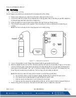
The Line (L) and Neutral (N) wires should be stripped 1/4 in. (6.5 mm), insert the wire into the ”L” and “N” wire
positions of the modular Fan/Power connector and tighten the screw clamp. Ensure that the wire cannot be easily
pulled from the connector. Plug the modular connection into the Fan/Power connection and ensure that it latches
into the header properly.
3.3.2.2
Fan Relay connection
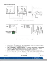
All of the SPDT Fan relay terminals are available at the Fan/Power modular connector. Each Fan relay terminal
normally open, common and normally closed (NO, COM and NC) can accommodate a wire size 12 to 24 AWG. To
install the wiring for the relays, disconnect the connector from the header. Strip the insulation of each wire back
approximately 1/4 in. (6.5 mm), insert the bare wire into the terminal and tighten the screw clamp. Ensure that the
wire cannot easily be pulled from the connector. Plug the modular connection into the Fan/Power connection and
ensure that it latches into the header properly.
3.3.2.3
Alarm Relay Connection
The external alarm connections (A and B) are available at the Alarm modular connector. There is no polarity for
these connections. To install the wiring for the alarm contacts, disconnect the connector from the header on the
detector. Strip the insulation of each wire back approximately 1/4 in. (6.5 mm), insert the bare wire into the terminal
and tighten the screw clamp. Ensure that the wire cannot easily be pulled from the connector. When the wires are
connected seat the modular connector into the header ensuring that the latch engages.
3.3.2.4
4-20 mA Signal connection
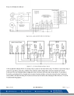
The positive and negative 4-20mA signal connections (+ and -) are available at the 4-20mA modular connector, a 2-
position connector. To install the wiring for the 4-20 mA contacts, disconnect the connector from the header on the
detector. Strip the insulation of each wire back approximately 1/4 in. (6.5 mm), insert the bare wire into the terminal
and tighten the screw clamp. Ensure that the wire cannot easily be pulled from the connector. When the wires are
connected seat the modular connector into the header ensuring that the latch engages.
NOTE
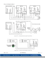
: The 4-20mA current loop outputs may be used with the Macurco DVP-120 control panel or other systems.
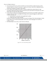
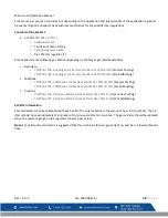
The 4-20mA signal connections to detectors should be size AWG18 (minimum) for short runs. Refer to the table for
recommended wire gauges. Do not bundle detector 4-20mA signal connections with AC power cables to prevent
electrical interference. If AC power connections must be bundled with the detector 4-20mA signal cables, the signal
connections should be made with twisted pair of the appropriate gauge, with an overall foil and braid shield. All
shields should be terminated at the DVP-120 end of the cable only. A ground stud is provided near the bottom left
corner of the DVP-120 panel.
Summary of Contents for GD-6
Page 2: ......
Page 35: ...Macurco GD Operation Manual REV 1 0 0 34 2900 0027 6 34 P a g e 9 2 Auto Test Menu bUZ...
Page 36: ...Macurco GD Operation Manual REV 1 0 0 34 2900 0027 6 35 P a g e 9 3 Configuration Menu CON...
Page 37: ...Macurco GD Operation Manual REV 1 0 0 34 2900 0027 6 36 P a g e...
Page 38: ...Macurco GD Operation Manual REV 1 0 0 34 2900 0027 6 37 P a g e...
Page 39: ...Macurco GD Operation Manual REV 1 0 0 34 2900 0027 6 38 P a g e...
Page 40: ...Macurco GD Operation Manual REV 1 0 0 34 2900 0027 6 39 P a g e...
Page 41: ...Macurco GD Operation Manual REV 1 0 0 34 2900 0027 6 40 P a g e...
Page 42: ...Macurco GD Operation Manual REV 1 0 0 34 2900 0027 6 41 P a g e 9 4 Select Test Menu tst...
Page 43: ...Macurco GD Operation Manual REV 1 0 0 34 2900 0027 6 42 P a g e 9 5 CAL Menu...
Page 44: ...Macurco GD Operation Manual REV 1 0 0 34 2900 0027 6 43 P a g e 9 6 Sensor Reset Menu Sen...
Page 45: ......
Page 47: ......
Page 49: ......
Page 94: ...Macurco GD Operation Manual REV 1 0 0 34 2900 0027 6 46 L a p a g e...
Page 95: ...Macurco GD Operation Manual REV 1 0 0 34 2900 0027 6 47 L a p a g e...
Page 96: ...Macurco GD Operation Manual REV 1 0 0 34 2900 0027 6 48 L a p a g e...
Page 97: ...Macurco GD Operation Manual REV 1 0 0 34 2900 0027 6 49 L a p a g e...
Page 98: ...Macurco GD Operation Manual REV 1 0 0 34 2900 0027 6 50 L a p a g e...
Page 100: ...Macurco GD Operation Manual REV 1 0 0 34 2900 0027 6 52 L a p a g e 9 5 CAL Menu...
Page 102: ......
Page 104: ......
Page 106: ......
Page 149: ...Macurco GD Operation Manual REV 1 0 0 34 2900 0027 6 44 p g i n a 9 3 Men de configuraci n CON...
Page 150: ...Macurco GD Operation Manual REV 1 0 0 34 2900 0027 6 45 p g i n a...
Page 151: ...Macurco GD Operation Manual REV 1 0 0 34 2900 0027 6 46 p g i n a...
Page 152: ...Macurco GD Operation Manual REV 1 0 0 34 2900 0027 6 47 p g i n a...
Page 153: ...Macurco GD Operation Manual REV 1 0 0 34 2900 0027 6 48 p g i n a...
Page 154: ...Macurco GD Operation Manual REV 1 0 0 34 2900 0027 6 49 p g i n a...
Page 156: ...Macurco GD Operation Manual REV 1 0 0 34 2900 0027 6 51 p g i n a 9 5 Men CAL...
Page 158: ......
Page 159: ......

