Macro-Tech 3600VZ Power Amplifier
Page 20
Reference Manual
4 Operation
4.1 Precautions
Although the Macro-Tech 3600VZ is protected from ex-
ternal faults, the following precautions should be fol-
lowed for safety and optimum operation:
1. There are important differences among the Ste-
reo, Bridge-Mono and Parallel-Mono operating
modes (see Section 3.3).
2. WARNING: Do not change the position of the
Stereo/Mono switch unless the amplifier is
first turned off.
3. CAUTION: In Parallel-Mono mode, a jumper is
used between the Channel 1 and Channel 2
red binding posts (amplifier outputs). Be sure
to remove this jumper for Bridge-Mono or
Stereo mode; otherwise inefficient operation,
high distortion and excessive heating will oc-
cur. Check the Stereo/Mono switch on the
back panel for proper position.
4. Turn the amplifier off and unplug it from the
AC mains before removing a PIP card.
5. Use care when making connections, selecting
signal sources and controlling the output level.
The load you save may be your own.
6. Do not short the ground lead of an output cable
to the input signal ground. This may form a
ground loop and cause oscillations.
7. Operate the amplifier from AC mains of not more
than 10% variation above or below the selected
line voltage and only the specified line fre-
quency.
8. Never connect the output to a power supply
output, battery or power main.
9. Tampering in the circuit by unqualified person-
nel, or making unauthorized circuit changes may
be extremely dangerous and may invalidate the
warranty.
Remember: Crown is not liable for damage that results
from overdriving components in your system.
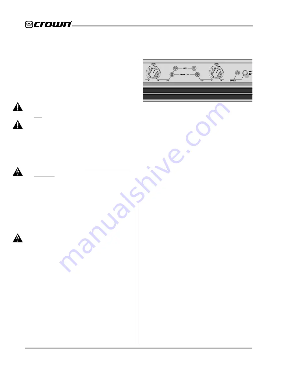
4.2 Indicators
The front panel has several helpful LED (light emitting
diode) indicators.
The amber
Enable indicator
is provided to show the
amplifier has been turned on (or enabled) and that the
low-voltage power supply is working. It does not indi-
cate the high
voltage supply status. As a result, disrup-
tion of the high voltage supplies has no effect on the
Enable indicator. This means that in the improbable
event that one or both channels overheat and cause a
shut down of the high voltage power supply, the Enable
indicator will remain on. However, the Signal/IOC indi-
cator lights to show that the output waveform does not
match the input.
The
ODEP indicators
provide a visual indication of the
operation of Crown’s patented Output Device Emula-
tion Protection (ODEP) circuitry. This circuitry protects
the amplifier output stages against heat damage by pro-
portionally limiting the drive level to the output stages.
This enables the amplifier to operate safely even under
severe operating conditions.
During normal operation, the ODEP indicators glow
brightly to indicate that the output stages are operating
within their thermal range (SOA - Safe Operating Area).
However, if an output stage begins to overheat, the
ODEP circuitry proportionally limits the drive signal and
the LEDs dim. In the unlikely event that the amplifier
exceeds the operating limits, ODEP shuts down the out-
put stages and the indicators turn off. The indicators
also turn off if the power supplies are put in standby
mode.
Note: The high voltage power supplies will temporarily
go into standby mode if their transformers get too hot or
if there is DC or heavy common-mode current in the
output.
The green
Signal/IOC indicators
provide the triple
functions of Signal Presence, Distortion, and Input Over-
load indicators. As signal presence indicators, they
flash with normal intensity in sync with the audio out-
puts. As IOC (Input/Output Comparator) indicators, they
flash brightly if there is any difference between the input
and output signal waveforms greater than 0.05%. Be-
cause transient distortion happens quickly, a 0.1 sec-
ond “hold delay” keeps the indicators on long enough
to be easily noticed. This IOC function verifies the
Fig. 4.1 Indicators


