Before carrying out any maintenance disconnect
the air supply to the pump and release the fluid
pressure in the system by pressing the lever on the
control gun.
Inspect your oil control gun daily for any signs of damage.
Replace any damaged parts or components as required.
CONTROL HANDLE DISASSEMBLY
Use a clean bench to carry out maintenance.
A)
Remove the oil hose from the control gun inlet swivel
(21).
B)
Unscrew and remove swivel (21) washer (19) and o’ring
(20) from the control gun inlet. (Clean or replace the
swivel strainer and o’ring if required).
Caution the swivel is under spring tension
D) Remove the screw (23), then unclip and remove the
trigger guard (22).
C) Remove valve spring (18), seal/valve body assembly (17).
and plunger (15).
LEVER and VALVE REMOVAL
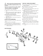
A) Using a 2.5mm allen key, remove the 2 handle screws
(10).
B) Remove lever (11), ease downwards.
C) Remove the washer (7), “O”Ring (8), then push the valve
cam (9) from the gun body (6), and remove “O”Ring (8).
CONTROL HANDLE REASSEMBLY
A) Clean and inspect all parts. Replace any suspect, worn or
damaged components.
Note: Lightly lubricate the valve cam before assembly.
B) Place “O”Ring (8) onto valve cam (9).
Note: The cutout section in the middle of the valve cam (9)
must face the inlet swivel (21).
C) Replace the valve cam (9) into the body (6). Note the
orientation shown on the assembly drawing. Fit the
second “O”Ring (8) and washer (7).
D) Slide lever assembly (11) into position and replace the two
allen screws (10). (Use Loctite or similar sealant).
E) Replace plunger (15).
Note: The end hole in the plunger must face the gun outlet.
F) Replace the seal/valve body assembly (17), and spring
(18) and replace into the gun body (6).
Note: Install the spring, small end first.
H) Replace washer (19), o’ring (20) on to the swivel assembly
(21), and screw firmly into place (Use Loctite or similar
sealant).
Note: After assembly ensure the handle latch is operating
correctly.
2
G) Re-fit the trigger guard (22) and replace screw (23).
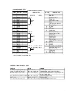
PARTS DIAGRAM
HGFNZ
1
2
3
4
5
6
7
8
9
10
11
8
10
12
13
14
15
18
19
20
21
22
23
Note: If the plunger has not been removed the cam will not
release from the body.
17


