background image


999674 – Revision B 


P a g e

 | 

28 of 44


6.7


Powered Auxiliary Hoist 

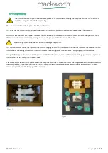
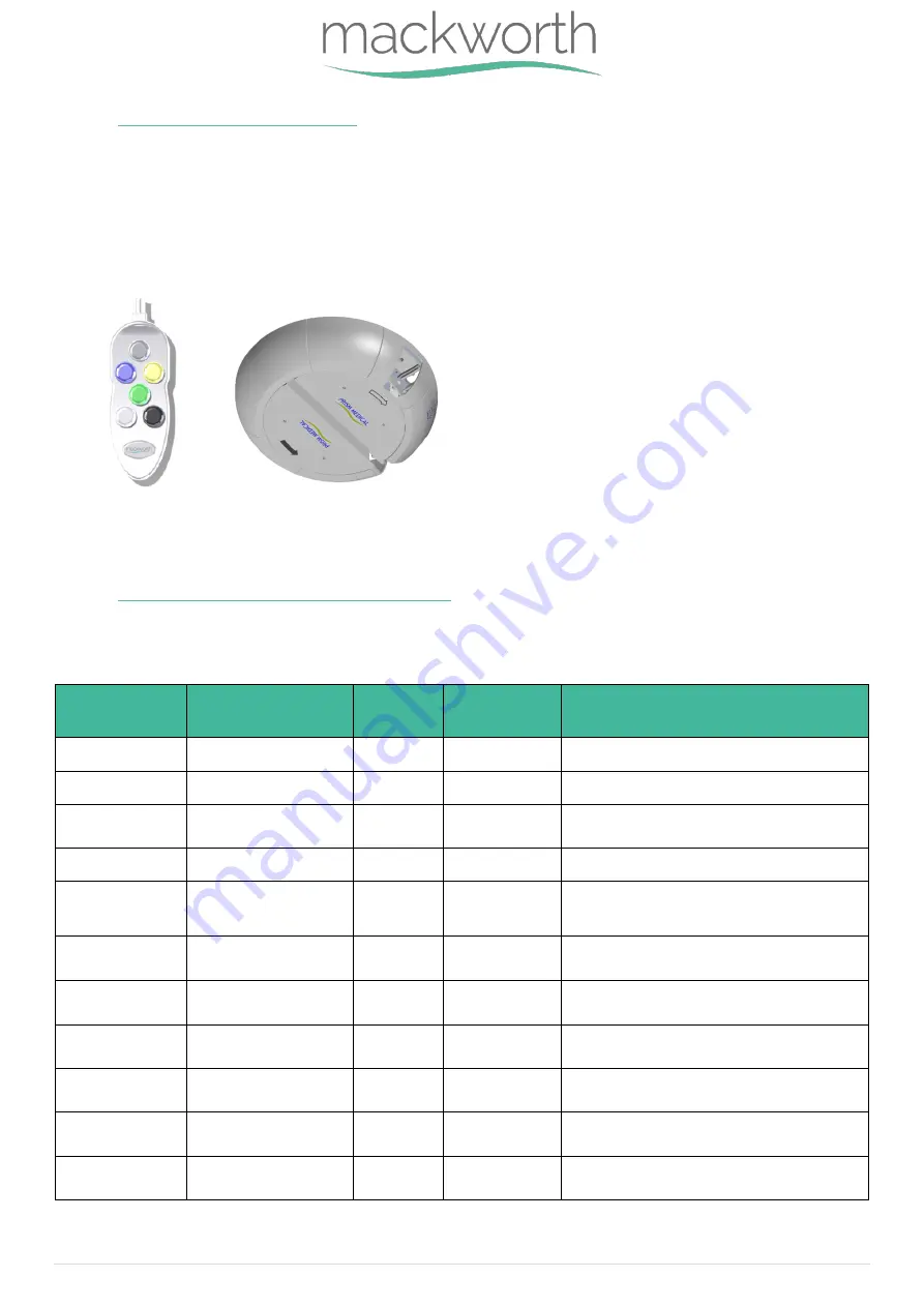
The TX Advanced with Powered Auxiliary option includes all the same features as a standard Powered or Manual TX Advanced. 

But this option includes the ability for the Hoist to communicate with Powered H-Systems, Powered Turntables or Powered 

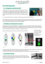
Pivoting Carry Bars. This communication can be done using the two additional buttons on the handset (Figure 36).  These are the 

White and Black buttons.  


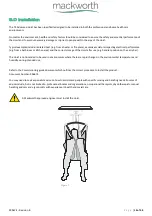
These buttons will communicate and move the H-System/Turntable or Powered Carry Bar in the direction indicated by the black 

and white arrows located on the underside of the optional system.  


For details on how to operate the Powered Turntable, Powered H-System and Powered Carry Bar with the Powered Auxiliary 

Hoist see the User Manuals for these products. 

6.8


LCD Display Screen Functionality 

The table below includes the details on all user display messages, it also includes the LED colour, the audible beeping and 

instructions on what actions to take when each message appears. This table may help for troubleshooting.  


Display 

Message 

Message 

explanation 

LED 

colour 

Beep sound 

Instruction 

LOW Batt!


Battery Status LOW


Orange 

1 Beep Repeat 

Place Hoist on charge as soon as possible


Charged


Batteries Fully Charged


Green 

None 

Batteries full - remove from charging dock


Charging


Charging Currently 

Active


Orange 

flashing 

None 

None - Batteries are charging


Up


Hoist Lifting Active


Green 

None 

None - Informative only


Down


Hoist Lowering Active


Green 

None 

None - Informative only


No Lim_Sw!


Limit Switch Fault


Green 

Constant 

Beep 

Contact Service Centre


UP: Inhibit!


Battery Capacity TOO 

LOW to Lift


Red 

3 Beep Repeat 

Place hoist on charge immediately


Up  Lim_Sw!


Up Limit Switch Active


Green 

None 

None - Informative only, 

press Down to continue


Down Lim_Sw!


Down Limit Switch 

Active


Green 

    None 

None - Informative only, 

press Up to continue


HIGH CURRENT


High Current D raw 

from Hoist Motor


Green 

Beep for 1 

Second 

Contact Service Centre


PM Due


Preventative 

Maintenance Due


Green 

Beep every 30 

minutes 

Contact Service Centre


Table 10


Figure 36


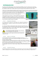
Figure 37


Summary of Contents for TX600

Page 1: ...Doc No 999674 Revision of document B Revision Date 10 05 2021 TX Advanced Ceiling Track Hoist User Manual...

Page 2: ...Installation 14 4 0 Type BF Applied parts 15 5 0 Frequently Used Functions 15 5 1 Carry Bar 15 5 2 Sling 16 5 3 Connecting the Handset to the Hoist 23 6 0 Hoist Operation 24 6 1 Turning the Hoist ON a...

Page 3: ...7 4 Standards Applied 31 8 0 Environmental Storage and Operating Conditions 32 8 1 Normal operating conditions 32 8 2 Shipping and storage conditions 32 9 0 Disposal 33 10 0 Fault Finding 34 11 0 Gene...

Page 4: ...Type 3 TX600 Advanced RTC 122709 Type 3 TX440 Advanced RTC 122713 Type 4 TX600 Advanced RTC 122714 Type 4 TX440 Advanced RTC 122718 Type 5 TX600 Advanced RTC 122719 Type 5 TX440 Advanced MTCC 122616 T...

Page 5: ...s in this manual may result in injury to the operator and or client and or damage to the Ceiling Track Hoist or related components Contents of this manual are subject to change without prior notice Do...

Page 6: ...which protection against electric shock does not rely on basic insulation only Safe Working Load represents the maximum load rated for safe operation Manufacturer Date of manufacture Packaging indicat...

Page 7: ...e person being moved the simple to use Hoist maximises the amount of care provided to the person The TX Advanced Hoist is a Ceiling Track Hoist and should only be used whilst on the Ceiling Track It h...

Page 8: ...d parts Do not remove cover screws or open the Hoist unit as this will VOID THE GUARANTEE WARRANTY Never expose the TX Advanced Hoist directly to water Your guarantee does not cover any misuse or abus...

Page 9: ...If during the use of this device or as a result of its use a serious incident has occurred please report it to the manufacturer and to your national authority Electric Shock Do not insert any objects...

Page 10: ...manufactured and tested in accordance with the legal requirements for the environment in which the device will be used within Pacemakers defibrillators and other medical devices should be manufacture...

Page 11: ...sting 2 7 Table 4 Immunity to Electrostatic discharge Enclosure Port Pass IEC 61000 4 2 2008 Configuration and Mode Test setup standby 2 4 7 1 1 Electromagnetic Radiation Disturbance Pass CISPR 11 200...

Page 12: ...Traverse Item Description Part Numbers 1 TX Advanced Hoist See Table 1 2 Carry Bar 300024 3 Handset MT 122349 PT 122075 4 Hoist Charger Track Type 1 122100 5 Allen Key 122093 6 User Manual 999053 TX...

Page 13: ...en using a sharp knife be careful not to damage the product This section will summarize the layout of the Hoist Packaging and what is included in the Box It is recommended a knife is used for smoother...

Page 14: ...n area and the correct storage of the Hoist after use e g handset position on the carry bar The Hoist is not intended to be used in environments where there are rapid changes in the environmental temp...

Page 15: ...site to the hoist in the following way 1 On the hook move the locking mechanism into the hook by pressing down on the tab Figure 6 and 7 2 With the carry bar positioned sideways along the length of th...

Page 16: ...15 3 After positioning the loop below the locking mechanism Figure 15 release the spring locking mechanism to secure the sling loop Figure 16 Make sure the required loop s are on the correct hooks an...

Page 17: ...ay the Handset can be connected therefore it is not possible to incorrectly mate the two parts Once the two parts have been aligned ensure that the Handset is pushed into the Grommet properly with bot...

Page 18: ...wered to the correct height for attaching the sling or positioning an individual The UP DOWN functions of the handset buttons are in relation to the travel of the Hoist That is the grey button at the...

Page 19: ...there is a patient being transferred ensure they are at a reasonable height above the ground to ensure they are not being dragged along the floor or hit any obstructions Always ensure the direction o...

Page 20: ...fitted during the installation of the Hoist Figure 30 To Traverse the TX Advanced simply manually or power traverse the Hoist along the track to the charging dock at the far end of the track Once the...

Page 21: ...is located underneath the Hoist unit Figure 29 Continue to pull down on the emergency red cord until the person is safely lowered to the desired position The unit will continue beeping until the red...

Page 22: ...LED colour the audible beeping and instructions on what actions to take when each message appears This table may help for troubleshooting Display Message Message explanation LED colour Beep sound Inst...

Page 23: ...ended use However should the device or the installed system require modification please consult your local Mackworth dealer to arrange a date and time to assess the required changes to the system If t...

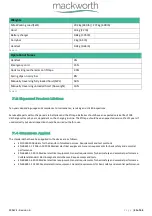
Page 24: ...1 16 s Lifting Speed No Weight 64 52 mm s 2 54 s Lowering Speed 272 kg 600 lb 54 48 mm s 2 14 s Lowering Speed No Weight 60 75mm s 2 39 s Stopping Distances Up 272 kg 600 lb 10 mm 0 39 Stopping Dista...

Page 25: ...on the charging routine The lift tape should have an expected service life of 2 years if used correctly but visual inspection should be carried out before use 7 4 Standards Applied The standards that...

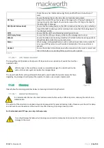
Page 26: ...will help the user through all ranges of lighting The Specification of the hoist dictates that normal use would occur during ambient luminance 50 500 lux Additional as the hoist is designed for indoo...

Page 27: ...oper method of disposal of potentially biohazardous parts and accessories The relevant components utilised in the manufacture of the device that can be recycled at the end of the device life are Fully...

Page 28: ...teries may be low and require charging Refer to the section 6 5 Charging The Hoist Charge the hoist for at least one hour and then try to raise lower the carry bar If none of these resolve the fault D...

Page 29: ...Notice any change in the performance Want to report an unexpected occurrence Want to arrange a service Need to ascertain necessary information for replacement parts and components Contact details of...

Page 30: ...is present Handset Ensure the Handset is functional ensure the connection to the Hoist is correct and that all the buttons are working before operation with a patient The image Figure 39 indicates a...

Page 31: ...e should be for 5 minutes to prevent any virucidal infections without a degradation to the functionality of the device 5 minutes is a recommended contact time The device can withstand a longer contact...

Page 32: ...a full review of the data please follow the link below http www nhsggc org uk media 236215 msds actichlor plus pdf 12 0 Warranty This guarantee does not affect or in any way limit your Statutory Right...

Page 33: ...999674 Revision B P a g e 39 of 44 13 0 Service Record History Complete this section after each service repair inspection and or maintenance...

Page 34: ...999674 Revision B P a g e 40 of 44...

Page 35: ...999674 Revision B P a g e 41 of 44...

Page 36: ...999674 Revision B P a g e 42 of 44...

Page 37: ...999674 Revision B P a g e 43 of 44...

Page 38: ...any errors or omissions Mackworth operates a policy of continuous improvement Specifications and other data are subject to change without notice Dealer contact details Prism Medical UK Contact details...

Reviews: