background image

11

Quick-Start Guide

Quick

-Star

t Guide

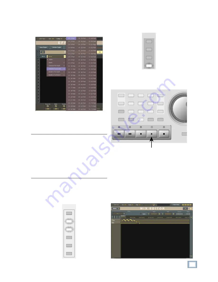
21.  In the Reverb panel, click the Src L drop-down 

box and select Channel Post Insert > Ch. 1 
Post. This places the reverb in the post-insert 
loop on channel 1.

22.  Adjust the reverb parameters using the V-Pots 

at the bottom of the Effects Rack. You should 
see the Left Input and Output meters move as 
you talk or sing into the microphone.

Note:

 A more typical use for an effect in the Ef-

fects Rack might be to route several channels to an 
Aux Send; for example, all the background vocals 
to Aux Send 1. Route Aux Send 1 to the input of 
the effect in the Effects Rack by selecting it in the 
Src (Source) drop-down box. The Aux 1 master 
fader (Masters Fader Bank) is used to control the 
amount of signal being sent to the effect. Return 
the effects signal to the signal path by selecting the 
effect's output for the input of an unused channel.

To write some basic automation:

23.  In the AUTOMATION MODES section of the 

console, select FADER and MUTE. Turn off the 
BYPASS button.

AUTOMATION

MODES

TRIM

PAN

ALL

BYPASS

FADER

MUTE

24.  Select the WRITE button in the ASSIGN BUT-

TON SETUP section of the console. Press the 
ASSIGN button on channel 1.

ASSIGN BUTTON

SETUP

REC

L - R

READ

WRITE

25.  Start running time code by pressing the PLAY 

button in the Transport section of the console. 
You can see the time code in the upper-right 
corner of the screen.

REWIND

FAST FWD

PLAY

STOP

RECORD

1

2

0

3

4

5

6

7

8

9

EDIT

START

END

SNAP

SHOT

LOCATE

SCRUB

STORE

SET

ENTER

ON

STOP

LOOP

START

26.  Move the channel 1 fader up and down a few 

times and press the mute button on channel 1.

27.  Press the STOP button in the Transport section 

and press REWIND to return the time code to zero.

28.  Press the PLAY button and the fader moves and 

mute will playback from automation.

29.  You can open the Mix Editor (Windows > Mix 

Editor) to see the automation moves. Select 
Channels > Ch. 1 in the Show drop-down box at 
the top of the Mix Editor to see the recorded fader 
moves and mute action relative to the time code.

Summary of Contents for X.200

Page 1: ...QUICK START GUIDE X 200...

Page 2: ...ARD 5 8 SYNCCARD 6 OtherConnections 6 9 FOOTSWITCH1and2 6 10 SERIAL9PIN 6 11 MIDIINandOUT 6 12 ETHERNET 6 13 USB 6 14 IECPowerReceptacle 6 15 PowerSwitch 7 MoreConnections 7 16 Mouse 7 17 Keyboard 7 1...

Page 3: ...for future reference i e insurance claims tech support return authorization etc Purchased at Date of purchase Thank you for choosing a Mackie Digital X Bus for your next generation digital recording...

Page 4: ...x B in the Digital X Bus X 200 Owner s Manual for a wiring diagram of these connectors Once you ve unpacked your new Digital X Bus you ll want to posi tion it where you can sit comfort ably and reach...

Page 5: ...card to find out if it supports the double fast or single wire method 6 FIREWIRE CARD The FireWire card uses the IEEE 1394 protocol for connecting digital devices It currently provides 24 inputs and...

Page 6: ...when connecting to equipment with transport con trols and a position display The MIDI connectors can also be used to control your DAW application when the MIDI fader bank is selected DAW Bank You can...

Page 7: ...These are connections to the motherboard and include four additional USB connections and the PS 2 style mouse and keyboard connections To access the connectors 1 First turn off the Digital X Bus sele...

Page 8: ...ns are a row of rotary con trols called V Pots which is short for virtual potenti ometer Again unlike an analog console where a rotary pot can control one function a digital console allows you to assi...

Page 9: ...he power amplifier monitor speaker combo or a set of stereo headphones 1 microphone Appropriate cable to connect the microphone to your particular input card Cables to connect the speaker outputs to t...

Page 10: ...ufacturers recommended setting 17 Talk or sing into the microphone while slowly turning up the level control in the CONTROL ROOM sec tion You should hear sound in the speakers and see the L R meters a...

Page 11: ...n 23 In the AUTOMATION MODES section of the console select FADER and MUTE Turn off the BYPASS button AUTOMATION MODES TRIM PAN ALL BYPASS FADER MUTE 24 Select the WRITE button in the ASSIGN BUT TON SE...

Page 12: ...In this case you might have three MIC LINE 4 CARDS installed in slots 1 3 A SLOTS for 24 analog inputs and three DIGITAL CARDS installed in slots 4 6 B SLOTS for 24 digital outputs By assigning the Ou...

Page 13: ...NG M G MAN F FIGURE E P PAT ATENT P T PENDING ENGINEERED BY D BY SYNC C SLOTS D SLOT B SLOTS A SLOTS MIDI IN FOOT SWITCH 1 2 MIDI OUT USB ETHERNET SERIAL 9 PIN 1 15V 9 V 9amp 6 p 60Hz 230V 4 5 V 4 5am...

Page 14: ...NG A G ARE T E TRADEMARKS O S OR R R REGISTERED T D TRADEMARKS O S OF L F LOUD T D TECH I H INC C TA TAPCO MACKIE A AND T D THE E RUNNING M G MAN F FIGURE E P PAT ATENT P T PENDING ENGINEERED BY D BY...

Page 15: ...z 230V 4 5 V 4 5amp 5 p 50Hz 1100 1100W M W Max Bass Guitar Direct Box Electric Guitar Aux Sends Channel Inserts or Master Inserts Returns Internal Effects Rack From Aux Sends Channel Inserts or Maste...

Page 16: ...ed Road NE Woodinville WA 98072 USA www mackie com sales mackie com United States and Canada 800 898 3211 Europe Asia Central and South America 425 487 4333 Fax 425 487 4337 Middle East and Africa 31...

Reviews: