J2
GROUND
SP-41R
REAR VIEW
DATA +
DATA –
3
0
3
6
9
15
30
55
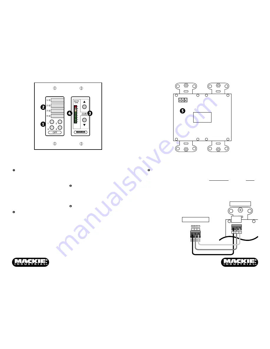
Front Panel Features
SELECT BUTTONS
Use to select the input source for the
SP1200 or SP2400. These buttons
correspond to the buttons on the front
panel of the SP1200/SP2400. The OFF
button deselects Inputs 1-4 and activates
the MIC/LINE input.
Due to the cross-fade that occurs when
switching input sources, there may be a
few seconds delay when attempting to
switch quickly between sources.
SELECT LED INDICATORS
Indicates the active input source. When
the LED is lit, the corresponding input
source is selected. When all the LEDs are
off, the OFF button is active and the MIC/
LINE input is selected.
Rear Panel Features
CONNECTOR (J2)
Connect the wires from the SP1200 or
SP2400 REMOTE bus to this connector on
the back of the SP-41R using the supplied
Phoenix-type connector. Strip the wire
back about 1/4", insert the wire as far as
it will go into the connector and tighten
down the screw with a small slot-head
screwdriver.
Use a high-quality three-conductor
shielded cable to make this connection,
such as Belden 8451, 9451, or equivalent.
1
2
3
REMOTE
SP1200/SP2400
REMOTE
J2
SP-41R
GROUND
DATA +
DATA
–
A space is provided next to each
indicating LED for inserting a 1/4" x 7/8"
label to identify the input source assigned
to each select button.
UP/DOWN VOLUME CONTROL
Use to adjust the output level for the
zone. Duplicates the function of the
MASTER VOLUME buttons on the SP1200/
SP2400 front panel.
LED DISPLAY
Indicates the level setting of the MASTER
VOLUME control.
Note:
The LED display does not indicate the
signal level in real time, but rather the level
setting of the MASTER VOLUME control.
The connector is wired as follows:
SP1200/SP2400
SP-41R
1 (Ground)
GND
2 (+ Data with +24V DC power)
+
3 (– Data with +24V DC power)
–


