Mackie Sound Palette SP2400 Instruction Manual Download Page 22

SP2400 – 22

Using the RS485 Connection

Each amplifier is equipped with an 

RS485

connection. These connectors are linked internally,
so if both amplifiers have the same 

AMP ADDRESS

assignment, the Input Selection and 

MASTER

VOLUME

 buttons track each other, since they are

assigned to the same zone. One side must have

AMP ADDRESS

 switch #6 in the Master position

(up), and the other side in the Slave position (down).

The same thing can be accomplished between

two SP2400s by connecting the amplifiers together
with the 

RS485

 connection. Again, be sure that

both amplifiers are assigned to the same zone
(

AMP ADDRESS

 switches 1-5), one is configured as

Master and the other Slave, and that no other
amplifiers are connected via the 

RS485

 port with

the same 

AMP ADDRESS

.

In this way, you can have one Remote control

operate both amplifiers that are assigned to the
same zone.

Note:

 The microprocessor polls the 

AMP

ADDRESS

 switch when it initializes at power-up. If a

change is made to the 

AMP ADDRESS

 switch, turn

the SP2400 off for five seconds, then turn it back
on again for the new settings to take effect.

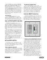
Using the SPLinker Sound Palette

Controller

The RS485 connection can also be used to

connect the SP2400 to a computer loaded with the
SPLinker software application. The PC-compatible
computer must have an RS485 port to properly
connect to the SP2400. It may be necessary to
install an RS485 interface card, or use an RS232
port with an RS232-to-RS485 converter.

The SPLinker is a PC-based graphical interface to

provide real-time monitoring and control for up to 32
zones. It provides individual program source
selection and volume control for each zone. Select
boxes are located at the bottom of each zone for
selecting multiple zones. All selected zones can
then be modified at the same time in the Multiple
settings box located on the right-hand side of the
screen.

Using a 3

rd

 Party Control System

The 

RS485

 connection can also be used to

interface with common third-party control systems.
Contact the third-party provider or Mackie Industrial
Technical Support to determine if your control
system is compatible with the SP2400.

Upgrading the Software

From time to time, Mackie Industrial will release

upgrades for the internal operating software in the
SP2400. This can be downloaded from our website
(

www.mackieindustrial.com

) to a PC-compatible

computer. Use the serial port on the computer to
connect to internal connectors on the SP2400's
CPU boards to transfer the data to the on-board
flash memory. Instructions will be provided when
upgrades are available.

Summary of Contents for Sound Palette SP2400

Page 1: ...IN AMP ADDRESS ZONE B RS485 REMOTE AMBIENT MIC MIC VOX AMP IN PRE OUT HIGH 12k FREQ MID LOW 80Hz U 15 15 U 15 15 U 15 15 1K 3K 400 8k 250 HIGH U 12 12 U 12 12 LOW GAIN ZONE A AMP IN PRE OUT PAGING MIC...

Page 2: ...sion cord receptacle or other outlet unless the blades can be fully inserted to prevent blade exposure Pour pr venir les chocs lectriques ne pas utiliser cette fiche polarise avec un prolongateur un p...

Page 3: ...d in U S A 2 INTRODUCTION The SP2400 is a microprocessor based dual channel music controller with two built in power amplifiers designed for use in a variety of installations requiring high performanc...

Page 4: ...he local program input signal connected here or the program signal on the expansion bus See Expansion In Out on page 18 for more information DIRECT OUTPUT is a buffered line level output providing the...

Page 5: ...signal source even numbered switches Move the switches up to select the local program source and down to select the remote external program source from the EXPANSION bus STEREO MONO switches configur...

Page 6: ...MANUFACTURED BY MACKIE DESIGNS INC WOODINVILLE WA MADE IN USA FABRIQUE AU USA ZONE B OUTPUT 100 70V 8 STEREO RIGHT 1 2 3 4 1 2 3 4 5 6 7 8 MONO STEREO LOCAL 1 2 3 4 REMOTE 1 2 3 4 ZONE A OUTPUT 100 70...

Page 7: ...Hz U 15 15 U 15 15 U 15 15 1K 3K 400 8k 250 HIGH U 12 12 U 12 12 LOW GAIN AMP IN PRE OUT PAGING MIC EXPANSION IN EXPANSION OUT THE FOLLOWING ARE TRADEMARKS OR REGISTERED TRADEMARKS OF MACKIE DESIGNS I...

Page 8: ...12 LOW GAIN AMP ADDRESS RS485 REMOTE AMBIENT MIC MIC VOX AMP IN PRE OUT HIGH 12k FREQ MID LOW 80Hz U 15 15 U 15 15 U 15 15 1K 3K 400 8k 250 HIGH U 12 12 U 12 12 LOW GAIN AMP IN PRE OUT PAGING MIC EXP...

Page 9: ...30dB U M I C G A I N 0 60 30dB 30dB U M I C G A I N 0 60 30dB 30dB U PHANTOM POWER 48V DC 12 1 5V 11 G 1 G G G INPUTS OUTPUTS 100 240V 50 60Hz 1A MAX THE FOLLOWING ARE TRADEMARKS OR REGISTERED TRADEMA...

Page 10: ...P ADDRESS switch 6 This allows the front panel buttons for both zones and all the remote controls to operate both zones simultaneously When an input is selected it is heard in both zones because Zone...

Page 11: ...et to the down position as well 40 Note The Paging Mic has priority over the system including Input 4 5 Is there a manual switch for paging Up to three switches can be connected to the SP2400 PAGING M...

Page 12: ...utput is configured for 8 ohm operation connect the speaker output directly to an 8 ohm load The amplifier will deliver up to 250 watts to each speaker If the amplifier is configured for either 70V or...

Page 13: ...ttings Note There are several settings that can be changed inside the SP2400 These settings should be made prior to installing the SP2400 CAUTION These servicing instructions are for use by qualified...

Page 14: ...the locations of the jumpers Note Each amplifier board must be configured separately On the Amplifier Boards J1 Jumper pins 1 and 2 for 8 ohm operation Jumper pins 2 and 3 for 70V or 100V operation J2...

Page 15: ...sis to allow proper ventilation If installing three or more SP2400s in a rack use a fan in the rack to move cool air in and warm air out of the rack s enclosure It may be necessary to provide a cool a...

Page 16: ...e instruction manual which is the only way to fully understand how the SP2400 works However the Quick Start provides a quick overview so you can get the SP2400 set up and working right away Make sure...

Page 17: ...ADDRESS switch 8 UP to enable the ambient mic See page 20 for more information on Using the Ambient Mic Expansion In Out If you are connecting two or more SP2400s in a system use the EXPANSION IN OUT...

Page 18: ...operate both amplifiers In a zone configuration move the STEREO MONO switches down to combine the stereo signal into a mono signal for each program source Set the AMP ADDRESS switches to different add...

Page 19: ...u let go of the switch the music begins to ramp up to its original volume Note 2 When the manual switch is off the voice activated VOX control for the paging mic is still operational Ensure that the P...

Page 20: ...ibration Proce dure when used with Ambient Mic 1 Perform the Ambient Microphone Calibration Procedure described above 2 Switch the ambient mic OFF AMP ADDRESS switch 8 down 3 Adjust the MASTER VOLUME...

Page 21: ...Speaker Connection If the SP2400 is not being used in a distributed speaker system you can reconfigure the amplifiers to drive an 8 ohm load Each amplifier can provide up to 250 watts into an 8 ohm lo...

Page 22: ...connect the SP2400 to a computer loaded with the SPLinker software application The PC compatible computer must have an RS485 port to properly connect to the SP2400 It may be necessary to install an RS...

Page 23: ...TO EXPANSION I O BUS ASSIGN TO EXPANSION I O BUS ASSIGN TO EXPANSION I O TO EXPANSION I O FROM EXPANSION I O FROM EXPANSION I O FROM EXPANSION I O FROM EXPANSION I O FROM EXPANSION I O FROM EXPANSION...

Page 24: ...position 30 dB 100V position Maximum Input Level 12 volts P P 15 dBu Rise Time 5 S Slew Rate 17 V S Preamplifier Section Input Levels Program Inputs 10 dBu to 10 dBu for maximum output level with inte...

Page 25: ...y important Mackie Industrial is not responsible for any damage that occurs during shipping due to non conventional packaging Original packaging helps to minimize the possibility of shipping damage 3...

Page 26: ...operation Press 3 on Power Up Paging Mic Level Adjustment Press and hold the Input 3 button while powering up the SP2400 Release the Input 3 button The lowest Paging Mic level is indicated on the LED...

Page 27: ...3 R6 D1 F1 J3 J1 J4 J2 J8 J5 J11 J14 J9 J6 J10 J7 J13 J12 D2 JP1 R5 K1 R2 C2 4A SB 250V BROWN BLUE YELLOW YELLOW RED BLACK BLACK RED YELLOW YELLOW RED BLACK RED BLACK REMOVE JUMPER FOR 230V SP2400 230...

Page 28: ...SP2400 Music Controller Mackie Industrial 16220 Wood Red Rd NE Woodinville WA 98072 USA 888 337 7404 Outside the U S 425 487 4333 Fax 425 487 4337 www mackieindustrial com...

Reviews: