Mackie ONYX 1640I Owner'S Manual Download Page 7

Owner's Manual   

7


Hookup Diagrams

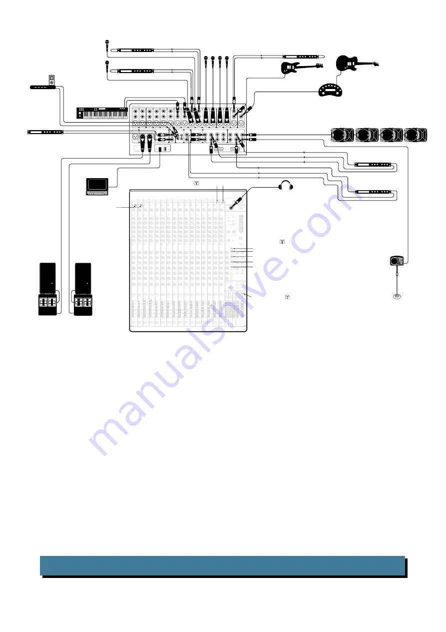
Typical Live Sound System

This diagram shows an electric guitar connected to the channel 1 line input via an amp modeler, a bass 

guitar connected directly to channel 2 (hi-z switch in), microphones connected to channel 3-8 mic inputs, 

and a keyboard connected to the channel 9 and 10 inputs. An iPod

®

 dock connects to the tape input. 

Headphones are used to monitor levels.

A dynamics processor is connected to the insert jack of channel 2 to work its magic on your bass. Vocal 

compressors are connected to the channel 7 and 8 inserts. A stereo compressor is connected to the main 

inserts.

SRM450v2 powered speakers are used as stage monitors for the band; they are connected to the aux 1 

send jack (in pre-fader mode). An SRM150 powered speaker receives a mono input from aux 2 send (in 

pre-fader mode), and is used as a monitor for your keyboard player. A reverb processor receives a mono 

input from aux 3 send (in post-fader mode), and its stereo outputs connect to the stereo aux 3 return inputs. 

A delay processor receives a mono input from aux 4 send (in post-fader mode), and its stereo outputs con-

nect to the stereo aux 4 return inputs. The aux 5 and 6 sends are sent directly to the computer for process-

ing by whatever VST plug-ins you may desire. These are then returned for playback on channels 15/16.

The club is driven by connecting a pair of powered subwoofers and a pair of HD1531 powered speakers 

to the main left and right outputs. Recording outputs 1-16 may be used in lieu of a splitter. All inputs fed 

into the monitor board may then be re-routed from these outputs into a separate front-of-house console. 

A laptop connects to a FireWire port, allowing the 2-channel main mix, and individual channels to be 

recorded. Any music (iTunes

®

, mp3s, or other pre-recorded audio) can be played back from the laptop. 

These can enter as either a source for the control room and phones, or any available channels.

SOLO

MUTE

SOLO

MUTE

SOLO

MUTE

SOLO

MUTE

SOLO

MUTE

SOLO

MUTE

SOLO

MUTE

SOLO

MUTE

SOLO

MUTE

SOLO

MUTE

SOLO

MUTE

SOLO

MUTE

SOLO

MUTE

SOLO

MUTE

SOLO

MUTE

SOLO

MUTE

EQ

EQ

EQ

EQ

EQ

EQ

EQ

EQ

EQ

EQ

EQ

EQ

EQ

EQ

EQ

EQ

SOLO

SOLO

SOLO

SOLO

SOLO

SOLO

1-2

3-4

dB

30

20

10

40

50

5

5

U

60

10

5

GAIN

4

CONTROL

ROOM

PHONES

L

R

SUB ASSIGN

L

R

L

R

L

R

MAIN

SUBS

SENDS

RETURNS

RUDE 

SOLO

SUB 3-4

FW 1-2

SUB 1-2

TAPE

ASSIGN TO

MAIN MIX

MAIN MIX

1

2

3

4

5

6

7

8

9

10

11

12

13

14

15

16

1

2

3

4

5

6

7

8

9

10

11

12

13

14

15

16

MAIN

MIX

SUB1

SUB4

SUB3

SUB2

SUB1

SUB4

SUB3

SUB2

4

3

2

2

1

1

6

4

2

1

5

6

3

PAN

AUX

AUX

AUX

AUX

AUX

AUX

AUX

AUX

AUX

AUX

AUX

AUX

AUX

AUX

AUX

AUX

CTRL ROOM/PHONES

SOURCE

LEVEL

MIC

EXTERNAL 

MIC

DESTINATION

AUX MASTER

TALKBACK

PHONES

AUX 1-6

1

2

3

4

5

6

7

8

9

10

11

12

13

14

15

16

HIGH

LOW

HIGH

LOW

1-2

3-4

GAIN

4

2

1

5

6

3

PAN

HIGH

LOW

HIGH

LOW

SOLO

LEVEL

TAPE IN

SOLO

MODE

L

R

POWER

1-2

3-4

GAIN

4

2

1

5

6

3

PAN

HIGH

LOW

HIGH

LOW

1-2

3-4

GAIN

4

2

1

5

6

3

PAN

HIGH

LOW

HIGH

LOW

1-2

3-4

GAIN

4

2

1

5

6

3

PAN

HIGH

LOW

HIGH

LOW

1-2

3-4

GAIN

4

2

1

5

6

3

PAN

HIGH

LOW

HIGH

LOW

1-2

3-4

GAIN

4

2

1

5

6

3

PAN

HIGH

LOW

HIGH

LOW

1-2

3-4

GAIN

4

2

1

5

6

3

PAN

HIGH

LOW

HIGH

LOW

1-2

3-4

GAIN

4

2

1

5

6

3

PAN

HIGH

LOW

HIGH

LOW

1-2

3-4

GAIN

4

2

1

5

6

3

PAN

HIGH

LOW

HIGH

LOW

1-2

3-4

GAIN

4

2

1

5

6

3

PAN

HIGH

LOW

HIGH

LOW

1-2

3-4

GAIN

4

2

1

5

6

3

PAN

HIGH

LOW

HIGH

LOW

1-2

3-4

GAIN

4

2

1

5

6

3

PAN

HIGH

LOW

HIGH

LOW

1-2

3-4

GAIN

4

2

1

5

6

3

PAN

HIGH

LOW

HIGH

LOW

1-2

3-4

GAIN

4

2

1

5

6

3

PAN

HIGH

LOW

HIGH

LOW

1-2

3-4

GAIN

4

2

1

5

6

3

3

PAN

HIGH

LOW

HIGH

LOW

AUX MASTERS

R

1

2

3

1

2

3

4

5

6

L

4

MAIN MIX

A LT E R N AT E   F I R E W I R E   A S S I G N M E N T S

SUBGROUPS

TALKBACK

RECORDING OUTS

1-8

9-16

SUB OUT

FIREWIRE

CTRL-RM OUT

TAPE

MAIN INSERT

IN

OUT

AUX SEND

AUX RETURN

3

3

R

L

R

R

L

R

L

R

L

R

L

R

L

1

4

2

5

1

2

4

3

1

6

4

2

R

L

R

L

MAIN OUT

HI-Z

L

1

INSERT

16

15

14

13

12

11

10

9

8

7

6

5

4

3

2

HI-Z

INSERT

LINE

INSERT

LINE

INSERT

LINE

INSERT

LINE

INSERT

LINE

INSERT

LINE

INSERT

LINE

INSERT

LINE

INSERT

LINE

INSERT

LINE

INSERT

LINE

INSERT

LINE

INSERT

LINE

INSERT

LINE

INSERT

Headphones

HD1531

Powered Speaker

Main Left

Powered

Subwoofer

HD1531

Powered Speaker

Main Right

Powered

Subwoofer

Microphones

Laptop Computer with 

audio production software

Amplifier

Modeler

Electric

Guitar

Bass

Guitar

press HI-Z 

button

Keyboard

Dynamics Processor (Bass)

Compressor (Vocals)

Compressor (Vocals)

Send

Return

Send

Return

iPod


Docking

Station

Stereo Compressor

SRM150

Powered Monitor

for keyboard player

(Aux Send 2)

Reverb (Aux Send 3)

Delay (Aux Send 4)

Mackie SRM450v2 

Powered Speakers 

(Stage Monitors)

Aux Send 1

Set Aux 1 & 2 PRE for monitors (switch UP)

Set Aux 3 & 4 POST for external processors

    (switch DOWN)

press FW button (      ) to send 

main mix to computer via 

FireWire channels 15 and 16

press FW button (      ) to receive 

 audio playback from computer

Send

Return

press FW button (      ) to send Auxes 1-6 

to computer via FireWire channels 9-14

Send

L/R Return

Send

L/R Return

Summary of Contents for ONYX 1640I

Page 1: ...HIGH MID FREQ LOW MID FREQ 40dB U 20dB U 20 30 40 60 L R MAX O O MAX O O MAX O O MAX O O MAX O O MAX O O SEND PRE POST OL 10 0 20 SUB ASSIGN MAIN MIX 1 2 3 4 GAIN 4 2 1 5 6 3 PAN HIGH 12kHz LOW 80Hz U...

Page 2: ...adian Department of Communications ATTENTION Le pr sent appareil num rique n met pas de bruits radio lectriques d passant las limites applicables aux appareils num riques de class A de class B selon l...

Page 3: ...rn them on last This will reduce the chance of turn on or turn off thumps Always turn down the phones level when making connections pressing solo or doing anything that may cause loudness in the head...

Page 4: ...erful Effects Engine With six aux sends routable to your DAW the 1640i al lows you to use your favorite plug in as a realtime effect Just route an aux send to your DAW apply the plug in and assign you...

Page 5: ...paragraphs This icon marks infor mation that is critically important or unique to the mixer For your own good read them and remember them This icon will lead you to some explanations of features and...

Page 6: ...DS 1 6 16 36 PAN 17 37 MUTE 17 38 CHANNEL FADER 17 39 20 0 10 AND OL LEDS 17 40 ASSIGN 17 41 SOLO 18 CONTROL ROOM PHONES AND METERS 19 42 HEADPHONE OUTPUT 19 43 LAMP 19 44 MAIN MIX 19 45 TAPE SUB 1 4...

Page 7: ...APE ASSIGN TO MAIN MIX MAIN MIX 1 2 3 4 5 6 7 8 9 10 11 12 13 14 15 16 1 2 3 4 5 6 7 8 9 10 11 12 13 14 15 16 MAIN MIX SUB1 SUB4 SUB3 SUB2 SUB1 SUB4 SUB3 SUB2 4 3 2 2 1 1 6 4 2 1 5 6 3 PAN AUX AUX AUX...

Page 8: ...1 SUB4 SUB3 SUB2 4 3 2 2 1 1 6 4 2 1 5 6 3 PAN AUX AUX AUX AUX AUX AUX AUX AUX AUX AUX AUX AUX AUX AUX AUX AUX CTRL ROOM PHONES SOURCE LEVEL MIC EXTERNAL MIC DESTINATION AUX MASTER TALKBACK PHONES AUX...

Page 9: ...UB3 SUB2 4 3 2 2 1 1 6 4 2 1 5 6 3 PAN AUX AUX AUX AUX AUX AUX AUX AUX AUX AUX AUX AUX AUX AUX AUX AUX CTRL ROOM PHONES SOURCE LEVEL MIC EXTERNAL MIC DESTINATION AUX MASTER TALKBACK PHONES AUX 1 6 1 2...

Page 10: ...AN HIGH 12kHz LOW 80Hz U 15 15 U 15 15 U 15 15 U 15 15 8k 400 2k 2k 100 400 HIGH MID FREQ LOW MID FREQ 40dB U 20dB U 20 30 40 60 L R MAX O O MAX O O MAX O O MAX O O MAX O O MAX O O SEND PRE POST GAIN...

Page 11: ...ps feature our Onyx design with higher fidelity and headroom rivaling any standalone mic preamp on the market today The XLR inputs are wired as follows Pin 1 Shield or ground Pin 2 Positive or hot Pin...

Page 12: ...ernal processor graphic equal izer or compressor limiter or directly to the inputs of the main amplifier 11 MONO OUT This 1 4 TRS output connector provides a balanced or unbalanced line level signal t...

Page 13: ...return input and the mono signals will ap pear on both sides of the main mix 19 AUX SENDS 1 6 These 1 4 TRS connectors allow you to send balanced or unbalanced line level outputs to external effects d...

Page 14: ...T OL 10 0 20 SUB ASSIGN MAIN MIX 1 2 3 4 GAIN 4 2 1 5 6 3 PAN HIGH 12kHz LOW 80Hz U 15 15 U 15 15 U 15 15 U 15 15 8k 400 2k 2k 100 400 HIGH MID FREQ LOW MID FREQ 40dB U 20dB U 20 30 40 60 L R MAX O O...

Page 15: ...h channel at optimal internal operating levels If the signal originates through the mic XLR jack there will be 0 dB of gain with the knob fully down ramping to 60 dB of gain fully up Through the 1 4 l...

Page 16: ...t needed When this button is out the EQ controls have no effect on the signal You may use this switch to make an A B comparison between the EQ d signal and the signal without EQ We have completely red...

Page 17: ...gnal when a channel is muted The LED next to the mute switch illuminates when the mute switch is engaged 38 CHANNEL FADER This is the last control in a channel s signal path and it adjusts the level o...

Page 18: ...ores telling everyone that I wrote the manual for that Let me be your main mix However if you are printing tracks via the recording outs 20 or via FireWire 3 the channel assignment switches no longer...

Page 19: ...ones and to check the main mix levels in the meters In addition to the main mix you can listen to any combination of tape FireWire and recording outs depending on which of these switches 45 is engaged...

Page 20: ...h the main mix lines to the source matrix will be discon nected from the control room and phones outputs to prevent feedback 3 If you have tape as your source matrix selec tion and then engage this sw...

Page 21: ...rs are not controlled by the control room knob 47 you would not want that anyway What you do want to see is the actual channel level on the meters regardless of how loud the signals output may be With...

Page 22: ...s or not used at all 55 MASTER AUX SENDS 1 6 These knobs provide overall control over the aux send levels just before they are delivered to the aux send outputs 19 These knobs go from off to 15 db whe...

Page 23: ...hannel strip These two knobs feed their respective stereo aux return signals to a mono summing amp and then to aux 5 feeds aux return 1 to aux send 5 master and to aux 6 feeds aux return 2 to aux send...

Page 24: ...click track directly into the main mix but you do not want the mixdown deck or the audience to hear it Therefore you may route it to the control room and phones output instead Similarily it may be us...

Page 25: ...TION PHONES AUX 1 6 Push in the phones switch to route the talkback signal to the headphones Use this to communicate with the talent in the studio through the headphones during a re cording session Wh...

Page 26: ...ect s output to whatever the final destination is usually a multitrack recorder The subgroup signal is off when its fader is fully down the U marking is unity gain and fully up provides 10 dB addition...

Page 27: ...x switch 44 is engaged The main mix signals are off with the knob fully down the U marking is unity gain and fully up provides 10 dB of additional gain This additional gain will typically never be nee...

Page 28: ...n case one of your external pieces has a problem Make sure that you are not overdriving your amplifiers Check the loudspeaker average load impedance is not less than the minimum your amplifier can han...

Page 29: ...lug is connected tip to signal send output from mixer ring to signal return input back into mixer and sleeve to ground earth 1 4 TS Phone Plugs and Jacks TS stands for Tip Sleeve the two connections a...

Page 30: ...loop TIP SEND to effect RING RETURN from effect MONO PLUG MONO PLUG STEREO PLUG Figure G DB25 Connectors The Recording Outs on the back of the Onyx 1640i provide balanced direct outputs for channels...

Page 31: ...4 dBu in 0 dB gain 4 dBu out 0 005 Mic input at insert 10 dBu in 20 dB gain 20 Hz to 20 kHz bandwidth 0 0007 Stereo channel line input to any output 4 dBu in all gain stages at unity 4 dBu out 0 005...

Page 32: ...other brand names mentioned are trademarks or registered trademarks of their respective holders and are hereby acknowledged The technical writer responsible for this manual thinks that his editor is a...

Page 33: ...in R R L aux 6 pre aux 5 pre pfl logic Main 4 3 Sub aux 6 post aux 5 post aux 4 pre aux 3 pre aux 4 post aux 3 post afl R afl L 2 1 aux 2 pre aux 1 pre aux 2 post aux 1 post CR in L CR in R L R Aux Re...

Page 34: ...nnections 2 The Pod can be fitted on the back of the mixer with the connections pointing out the back This will take up 12 rack spaces Allow one or two extra spaces for making your connections Details...

Page 35: ...ure 1 Turn off the mixer and disconnect the power cord and all connecting cords 2 Place the mixer face down on a soft and dry flat surface 3 Remove the 22 screws as shown below and keep them handy for...

Page 36: ...ht back on the Pod until it stops 5 Rotate Pod as shown below Hold both sides of the Pod to keep the travel even Move the Pod all the way back until it stops and the bottom surface of the Pod is paral...

Page 37: ...ack ears to the mixer using the same silver flathead screws removed from the side trim The rack ears are stamped with an R or L to denote which side of the mixer it goes on based on house view Finally...

Page 38: ...ds 2 Place the mixer face down on a soft and dry flat surface 3 Remove the 14 screws as shown below and keep them handy as you will need them again Only one screw from each side of the trim is removed...

Page 39: ...Rotate the Pod arms and reinstall the four arm screws Rotate the Pod so that the connection jacks are parallel to the top of the mixer Reinstall the two silver flathead screws through the side trim an...

Page 40: ...eces with the supplied screws Place the Pod bucket as shown Attach the Pod bucket to the mixer using the screws removed in step 3 Screw the Pod bucket to the Pod using the supplied screws Unscrew the...

Page 41: ...d the Onyx 1640i Pod section There is nothing else left to say about it no more instructions The thought of an almost nearly blank page is utterly intolerable though And this is included for a step th...

Page 42: ...s owner s manual you will not be reading this yet It s a bit of a paradox really because didn t you just read it Like this bit of text right now Hmm MackieWindowsFireWireAudioDriver InstallationInstru...

Page 43: ...audio applications such as iTunes or Windows Media Player InstallationforWindowsXP 1 Connect the FireWire cable from your Onyx 1640i to the computer 2 Power on your Onyx 1640i 3 The Windows XP applica...

Page 44: ...new software has been installed successfully and that the found new hardware wizard is com plete 11 Pack yourself a big lunch and go for a nice walk outside Have a picnic and lie back and dream Things...

Page 45: ...click Audio MIDI Setup 4 Click the Audio Devices tab and select Onyx i in the Properties For drop down box 5 Here you can see the settings for the mixer You can also choose it as your default input o...

Page 46: ...at they are post insert instead For example this allows for the use of an external processor on the mic signal sending the result to the FireWire while still being pre EQ Modifications Post FaderFireW...

Page 47: ...B U 20dB U 20 30 40 60 L R MAX O O MAX O O MAX O O MAX O O MAX O O MAX O O SEND PRE POST OL 10 0 20 SUB ASSIGN MAIN MIX 1 2 3 4 GAIN 4 2 1 5 6 3 PAN HIGH 12kHz LOW 80Hz U 15 15 U 15 15 U 15 15 U 15 15...

Page 48: ...MIC EXTERNAL MIC LINE FW 16 LINE FW 15 75Hz 18dB OCT 75Hz 18dB OCT DESTINATION AUX MASTER SENDS 1 6 TO FW 9 14 TALKBACK PHONES AUX 1 6 15 16 15 O O 15 O O 15 O O 10 O O 10 O O 10 O O 10 O O 10 O O 10...

Page 49: ...noncompliance within the Warranty Period to the Company at www mackie com support or by calling LOUD technical support at 1 800 898 3211 toll free in the U S and Canada during normal business hours Pa...

Page 50: ...Road NE Woodinville WA 98072 USA United States and Canada 800 898 3211 Europe Asia Central and South America 425 487 4333 Middle East and Africa 31 20 654 4000 Fax 425 487 4337 www mackie com E mail s...

Reviews: