background image

1202-VLZ3

POWER

ON

PHANTOM

ON

L MAIN

MAIN

OUTPUT

LEVEL

4

3

R/4

L/3

CHANNEL INSERT

BAL/UNBAL

BALANCED

BAL/UNBAL

ALT

OUTPUT

R

L

CONTROL

ROOM

SERIAL NUMBER

MANUFACTURING DATE

RISK OF ELECTRIC SHOCK

DO NOT OPEN

REPLACE WITH THE SAME TYPE FUSE AND RATING.

DISCONNECT SUPPLY CORD BEFORE CHANGING FUSE

UTILISE UN FUSIBLE DE RECHANGE DE MÊME TYPE.

DEBRANCHER AVANT DE REMPLACER LE FUSIBLE

WARNING: 

TO REDUCE THE RISK OF FIRE OR ELECTRIC SHOCK, DO NOT 

EXPOSE THIS EQUIPMENT TO RAIN OR MOISTURE. DO NOT REMOVE COVER. 

NO USER SERVICEABLE PARTS INSIDE. REFER SERVICING TO QUALIFIED PERSONNEL.

CAUTION

AVIS:


RISQUE DE CHOC ELECTRIQUE — NE PAS OUVRIR

2

1

( PRE-FADER / PRE EQ    TIP SEND / RING RETURN )

XDR

TM

 EXTENDED DYNAMIC RANGE MIC PREAMPLIFIERS ARE PROPRIETARY TO MACKIE DESIGNS, INC.

  -10

dBV 

GAIN

+15dB -45dB

 M

IC GAIN 

0

U

60

LINE IN 1

MIC 

1

LOW CUT

75 Hz

18dB/OCT

LOW CUT

75 Hz

18dB/OCT

LOW CUT

75 Hz

18dB/OCT

LOW CUT

75 Hz

18dB/OCT

BAL

OR

UNBAL

LINE IN 2

MIC 

2

BAL

OR

UNBAL

LINE IN 3

MIC 

3

BAL

OR

UNBAL

LINE IN 4

MIC 

4

BAL

OR

UNBAL

AUX SEND

1

2

1

2

R

R

L

L /MONO

ALL BAL/UNBAL

TAPE

INPUT

TAPE

OUTPUT

L

R

L

R

L

R

MAIN OUT

BAL/UNBAL

L

MONO

MONO

MONO

MONO

LINE IN 5–6

R

LINE IN 7–8

LINE IN 9–10

LINE IN 11–12

BAL

OR

UNBAL

L

R

BAL

OR

UNBAL

L

R

BAL

OR

UNBAL

L

R

BAL

OR

UNBAL

XDR 

MIC PRE 

XDR 

MIC PRE 

XDR 

MIC PRE 

XDR 

MIC PRE 

GAIN

+15dB -45dB

 M

IC GAIN 

0

U

60

  -10

dBV 

GAIN

+15dB-45dB

 M

IC GAIN 

0

U

60

  -10

dBV 

GAIN

+15dB -45dB

 M

IC GAIN 

0

U

60

  -10

dBV 

O

O

+15

O

O

+15

AUX

+15

-15

+15

-15

+15

-15

HI

12kHz

MID

2.5kHz

LOW

80Hz

HI

12kHz

MID

2.5kHz

LOW

80Hz

HI

12kHz

MID

2.5kHz

LOW

80Hz

HI

12kHz

MID

2.5kHz

LOW

80Hz

HI

12kHz

MID

2.5kHz

LOW

80Hz

HI

12kHz

MID

2.5kHz

LOW

80Hz

HI

12kHz

MID

2.5kHz

LOW

80Hz

HI

12kHz

MID

2.5kHz

LOW

80Hz

EQ

L R

1

MUTE

PAN

AUX

EQ

PAN

AUX

EQ

PAN

AUX

EQ

PAN

AUX

EQ

PAN

AUX

EQ

PAN

AUX

EQ

PAN

AUX

EQ

PAN

ALT 3–4

MUTE

ALT 3–4

MUTE

ALT 3–4

MUTE

ALT 3–4

MUTE

ALT 3–4

MUTE

ALT 3–4

MUTE

ALT 3–4

MUTE

ALT 3–4

PRE FADER

SOLO

LEVEL

2

PRE FADER

SOLO

LEVEL

3

PRE FADER

SOLO

LEVEL

4

PRE FADER

SOLO

LEVEL

5/6

PRE FADER

SOLO

LEVEL

7/8

PRE FADER

SOLO

LEVEL

9/10

PRE FADER

SOLO

LEVEL

11/12

PRE FADER

SOLO

LEVEL

POWER

RUDE

SOLO

LIGHT

LEVEL

SET

CONTROL

ROOM

SOURCE

ALT 3–4

TAPE

MAIN MIX

CLIP

LEFT RIGHT

0dB=0dBu

ASSIGN

TO MAIN MIX

MAIN MIX

/SUBMIX

CTL ROOM 

+12dB

O

O

U

+12dB

O

O

U

+12dB

O

O

U

+12dB

O

O

U

+12dB

O

O

U

+12dB

O

O

U

+12dB

O

O

U

+12dB

O

O

U

MAX

O

O

U

+12dB

O

O

U

U

U

O

O

+15

O

O

+15

U

U

O

O

+15

O

O

+15

U

U

O

O

+15

O

O

+15

U

U

U

U

U

+15

-15

+15

-15

+15

-15

L R

U

U

U

+15

-15

+15

-15

+15

-15

L R

U

U

U

+15

-15

+15

-15

+15

-15

L R

U

U

U

+15

-15

+15

-15

+15

-15

L R

U

U

U

+15

-15

+15

-15

+15

-15

L R

U

U

U

+15

-15

+15

-15

+15

-15

L R

U

U

U

+15

-15

+15

-15

+15

-15

L R

U

U

U

O

O

+15

O

O

+15

U

U

O

O

+15

O

O

+15

U

U

O

O

+15

O

O

+15

U

U

O

O

+15

O

O

+15

U

U

20

10

7

4

2

0

4

7

10

20

30

O W N E R ’ S   M A N U A L

12-Channel Mic/Line Mixer

Summary of Contents for 1202-VLZ3

Page 1: ...E XDR MIC PRE XDR MIC PRE GAIN 15dB 45dB M IC GAIN 0 U 60 10dBV GAIN 15dB 45dB M IC GAIN 0 U 60 10dBV GAIN 15dB 45dB M IC GAIN 0 U 60 10dBV O O 15 O O 15 AUX 15 15 15 15 15 15 HI 12kHz MID 2 5kHz LOW...

Page 2: ...dio interference regulations of the Canadian Department of Communications ATTENTION Le pr sent appareil num rique n met pas de bruits radio lectriques d passant las limites applicables aux appareils n...

Page 3: ...SELECTOR switch is set to the same voltage as your local AC mains supply see page 12 Level Setting Procedure Message to seasoned pros do not set levels using the old Turn the GAIN up until the clip l...

Page 4: ...each channel Output Section The output section on the right Throughout these sections you ll find illustrations with each feature numbered If you re curious about a feature simply locate it on the ap...

Page 5: ...HOOKUP DIAGRAMS 6 PATCHBAY DESCRIPTION 8 1 MIC INPUTS CHANNELS 1 4 8 2 LINE INPUTS CHANNELS 1 4 8 3 LOW CUT CHANNELS 1 4 9 4 GAIN CHANNELS 1 4 9 5 STEREO LINE INPUTS 9 6 IMAGINARY CONTROL 9 EFFECTS S...

Page 6: ...Vocal Mics Multi Effect Processor Digital Delay Powered Studio Monitors for Studio Headphone Distribution Amp Headphones for Studio 3 4 2 12 11 10 9 8 7 4 4 3 2 3 1 2 1 1 1 2 L R L R L R CHANNEL INSE...

Page 7: ...can be easily reconfigured to become a Mono PA setup A Stereo sources should feed the left mono side of channel input only B Pan each channel hard left C Connect Mono PA system to Left main output SR...

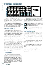
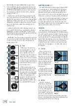
Page 8: ...m power with the mic preamps and can be driven by balanced or unbalanced sources at almost any level You can use these inputs for virtually any signal you ll come across from instrument levels as low...

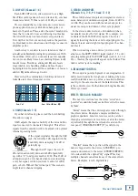
Page 9: ...tion on vocals Many times bass shelving EQ can really benefit voices Trouble is adding low EQ also boosts stage rumble mic handling clunks and breath pops Applying low cut removes all those problems s...

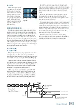
Page 10: ...er s inputs See also MAIN MIX 32 on page 16 Mono Out If you want to feed a mono signal to your tape deck or other device simply use an RCA Y cord to combine these outputs Do not attempt this with any...

Page 11: ...These 1 4 outputs are provided so you can listen to something other than the main mix The source is selected using the SOURCE MATRIX 33 switches see page 16 You can choose to listen to the main mix t...

Page 12: ...is perfectly normal Just like me Oh and my imagi nary friend Lazlo who helps me write all the manuals Say hello to the nice folks Lazlo POWER ON PHANTOM ON L MAIN MAIN OUTPUT LEVEL 4 3 R 4 L 3 CHANNE...

Page 13: ...up U LIKE UNITY GAIN Mackie mixers have a U symbol on almost every level control This U stands for unity gain meaning no change in signal level Once you have adjusted the input signal to line level y...

Page 14: ...u never heard Peaking means that certain frequencies form a hill around the center frequency 2 5 kHz in the case of the MID EQ 27 LOW EQ This control gives you up to 15 dB boost or cut below 80 Hz The...

Page 15: ...inde pendently of the channel s LEVEL control AUX 1 in post mode and AUX 2 are post LOW CUT post EQ and post LEVEL That is the sends obey the settings of these controls AUX 1 in PRE mode follows the E...

Page 16: ...es From there these signals all pass through the same level control 34 CONTROL ROOM SUBMIX This knob controls the levels of both the stereo CON TROL ROOM 15 and PHONES 12 outputs The con trol range is...

Page 17: ...monitors but your multitrack is playing back like mad 36 ASSIGN TO MAIN MIX Let s say you re doing a live show Intermission is near ing and you ll want to play a soothing CD for the crowd to prevent t...

Page 18: ...RN 7 to the main mix and once mixed together the dry and wet signals combine to create a glorious sound So armed with this knowledge let s visit the Auxiliary World 38 PRE or POST AUX 1 Besides being...

Page 19: ...at normalled connection is broken How does all this relate to the RETURN TO AUX 1 41 switch STEREO RETURN 1 s inputs are normalled to STEREO RETURN 2 If you have one effects device plug it into STEREO...

Page 20: ...a stereo pair try switching them around For example if a left output is presumed dead switch the left and right cords at the mixer end If the problem switches sides it s not the mixer Noise Turn the c...

Page 21: ...ed tip to signal high hot ring to signal low cold and sleeve to ground earth Unbalanced Send Return circuits When wired as a send return Y connector a 1 4 TRS jack or plug is connected tip to signal s...

Page 22: ...s and jacks are often used in home stereo and video equip ment and in many other applications Figure D They are unbalanced and electrically identical to a 1 4 TS phone plug or jack See Figure C Connec...

Page 23: ...rn cir cuit and will show up in the center of the stereo pair of buses it s assigned to or it can be panned with the PAN 26 control Y cord splitter cable TIP SEND RING IN TIP OUT RING RETURN TO MIXER...

Page 24: ...z Common Mode Rejection Ratio CMRR Mic in to Insert Send out max gain 1 kHz better than 70 dB Maximum Levels Mic in 22 dBu Tape in 16 dBu All other inputs 22 dBu Main Mix XLR out 28 dBu All other outp...

Page 25: ...ANNEL 1 OF 4 LINE IN L LINE IN R 3 BAND EQ LEVEL PAN MAIN ALT STEREO RETURN 1 L IN R IN STEREO RETURN 2 L IN MONO R IN GAIN GAIN RETURN TO AUX 1 MAIN MIX MAIN LEVEL 30dB PAD TAPE OUT L LINE OUT L BAL...

Page 26: ...MID 2 5kHz LOW 80Hz HI 12kHz MID 2 5kHz LOW 80Hz HI 12kHz MID 2 5kHz LOW 80Hz HI 12kHz MID 2 5kHz LOW 80Hz EQ L R 1 MUTE PAN AUX EQ PAN AUX EQ PAN AUX EQ PAN AUX EQ PAN AUX EQ PAN AUX EQ PAN AUX EQ P...

Page 27: ...ice representative will at its option either repair or replace any such nonconforming product provided that Customer gives notice of the noncompliance within the Warranty Period to the Company at www...

Page 28: ...Road NE Woodinville WA 98072 USA United States and Canada 800 898 3211 Europe Asia Central and South America 425 487 4333 Middle East and Africa 31 20 654 4000 Fax 425 487 4337 www mackie com E mail s...

Reviews: