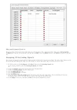
9. Map During Speed Agree to the Spindle At Speed signal.
10. Map During Zero Speed to the Spindle At Zero signal.
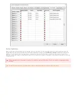
11. Select the Output Signals tab.
12. Enable the Spindle Fwd and the Spindle Rev signals.
13. The device name for both signals will be the same name that was in the RapidPath VFDs device list.
14. Map ioDeviceForward to the Spindle Fwd signal.
15. Map ioDeviceReverse to the Spindle Rev signal.
16. Select the Spindle tab.
17. Set the Max Spindle Motor RPM parameter appropriately.
18. Press Apply to save any changes and OK to close the configuration window.
There are multiple types of auxiliary spindles available, depending on your machine type. The VFD must first be told it
is an auxiliary spindle, and then it can be mapped to an available type. See
below for further
instructions.
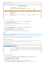
1. On the menu bar, click Configure -> Plugins -> RapidPath, then select the Other Devices tab.
2. Select the VFD to be configured by selecting it from the list on the left side.
3. Set the VFD Control parameter to Auxiliary.
4. Set the VFD Feedback parameter to Auxiliary.
5. Set the Max Motor Speed (RPM) appropriately for your motor.
6. Click Close.
The spindle can be tested as follows:
1. Enable the machine by pressing Reset.
2. Type an RPM into the spindle speed DRO on the main page.
3. Press FWD or REV on the operator panel.
4. The light on the button will blink until the spindle gets up to speed, then turn solid.
5. Press STOP to turn the spindle off.
6. When stopped, the spindle should be able to be turned by hand.
Make sure there is a speed commanded.
Make sure your spindle rate override is at 100%.
Make sure the correct digital outputs are mapped to the Spindle Fwd and Spindle Rev signals.
Make sure the correct digital inputs are mapped to the Spindle At Speed and Spindle At Zero signals.
Make sure the relevant Control and Feedback parameters are set to Mach.
Some machines have multiple spindle devices that need to be controlled independently, such as centerless grinders.
Servo spindles and VFDs can be set up as auxiliary spindles. First set the spindle device as auxiliary, then see some of
the options below.
Servo Spindle as Auxiliary Spindle
VFD as Auxiliary Spindle
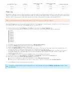
Most often used on router-type machines, the subspindle acts as a traditional spindle with it's own commanded speed,
separate from the main spindle. It is commandable from gcode and MDI with M103 S#### (Subspindle
Forward), M104 S#### (Subspindle Reverse), and M105 (Subspindle Stop).
VFD as Auxiliary Spindle
Spindle Testing
Check interferences and use low speeds when testing a spindle.
Troubleshooting
Auxiliary Spindles
Subspindle
Only VFDs can be configured as subspindles.

