(2) The position of the vise when loosened. ( Half opened).
(3) The position of the vise when loosened. (Completely opened).
To operate, proceed as follows:
1) Rise the arm 2” above the workpiece, close the cylinder valve to maintain the arm 2” above the
workpiece.
2) Put your workpiece on the table. Move the vise handle (a) upwards to an angle of 45 degree
(a-Half opened) to loosen the vise.
Move the vise jaw bracket against the workpiece by turning the rectangular handle (b) . Push
down on the vise handle (a) to lock the workpiece in position.
3) To loosen the workpiece from the vise, hold the workpiece and lift the vise handle (a) to a 90
degree position (completely opened). Remove workpiece.
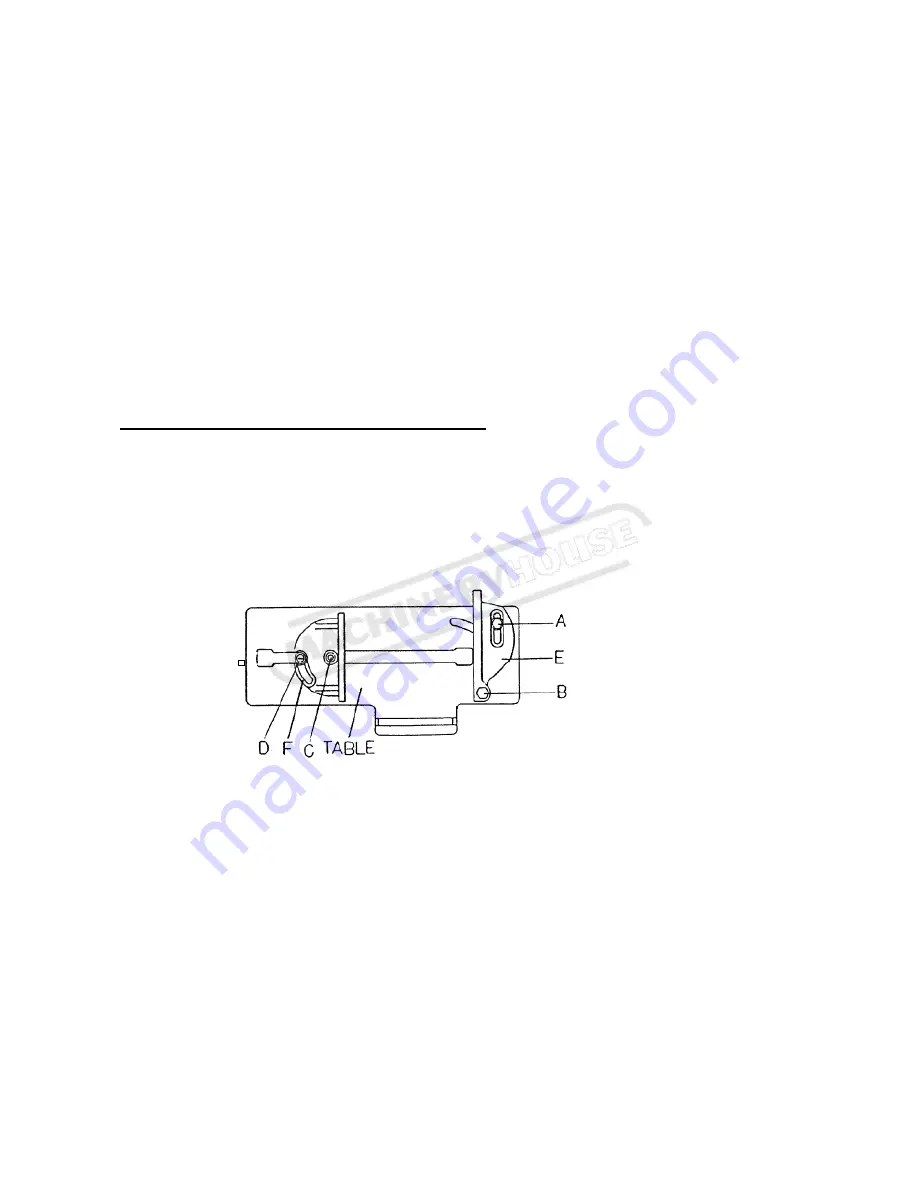
QUICK VISE ADJUSTMENT FOR ANGLE CUT
(1). Loosen the A. B. C. D. Screw.
(2). Adjust rear vise to the threaded hole position. (E)
(3). Set the scale to the desired angle.
(4). Adjust the front vise (F) to parallel the rear vise(E)
(5). Tighten the A. B. C. D. Screw.
11. BLADE GUIDE BEARING ADJUSTMENT
ATTENTION: This is the most important adjustment on your saw. It is impossible to get
satisfactory work from your saw if the blade guides are not properly adjusted. The blade guide
bearings on your metal. Cutting Band Saw are adjusted and power tested with several test cuts
before leaving the factory to insure proper setting The need for adjustment should rarely occur
when the saw is used properly. If the guides do get out of adjustment though, it is extremely
important to readjust immediately. If improper adjustment in maintained, the blade will not cut
straight, and if the situation is not corrected it will cause serious blade damage. Because guide
adjustment is a critical factor in the performance of your saw, it is always best to try a new blade to
see if this will correct poor cutting before beginning to adjust. If a blade becomes dull on one side
sooner than the other, for example, it will begin cutting crooked. A blade change will correct this
problem the gJide adjustment will not. If a new blade does not correct the problem, check the blade
15
Page 17
Instruction Manual for BS-912 (B014)
03/12/2014
Summary of Contents for BS-912
Page 24: ...CIRCUIT DIAGRAM 22 Page 24 Instruction Manual for BS 912 B014 03 12 2014...
Page 25: ...23 CE CE Page 25 Instruction Manual for BS 912 B014 03 12 2014...
Page 26: ...24 Page 26 Instruction Manual for BS 912 B014 03 12 2014...
Page 27: ...25 Page 27 Instruction Manual for BS 912 B014 03 12 2014...
Page 28: ...26 Page 28 Instruction Manual for BS 912 B014 03 12 2014...
Page 36: ...34 Page 36 Instruction Manual for BS 912 B014 03 12 2014...
Page 37: ...35 Page 37 Instruction Manual for BS 912 B014 03 12 2014...
Page 38: ...36 Page 38 Instruction Manual for BS 912 B014 03 12 2014...
Page 46: ...44 Page 46 Instruction Manual for BS 912 B014 03 12 2014...
Page 47: ...45 Page 47 Instruction Manual for BS 912 B014 03 12 2014...


