


215922
370
Revision A
1022892
A
C
B
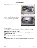
Figure 5.225: Drive Wheel Ready for Installation
5.
Position lifting device (A) under the wheel and raise the
wheel slightly.
6.
Position the wheel against the wheel drive hub so that air
valve (B) is on the outside while tread (C) points
cab-forward.
1011218
A
1
3
4
5
6
7
8
9
10
2
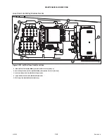
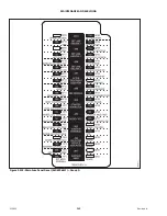
Figure 5.226: Tightening Sequence
–
10-Bolt Wheel
7.
Align the wheel rim with the studs on the hub. Push the
wheel onto the hub.
8.
Install and hand-tighten wheel nuts (A).
IMPORTANT:
To avoid damage to the wheel rims and studs, do
NOT
use
an impact wrench to tighten the nuts. The stud threads
must be clean and dry. Do
NOT
apply lubricant or anti-seize
compound to the stud threads. Do
NOT
overtighten the
wheel nuts.
9.
Torque the drive wheel nuts. For instructions, refer to
Tightening Drive Wheel Nuts, page 262
.
10. Repeat the tightening sequence two additional times, ensuring that the specified torque is achieved each time.
11. Repeat Step
to Step
in order to install the right drive wheel.
12. Raise the windrower, remove the stand, and lower the windrower to the ground.
13. Lower the windrower. Remove the jack. For instructions, refer to
Lowering Drive Wheel, page 370
.
14. Repeat the torque procedure every hour of operation until two consecutive checks confirm that there is no movement
of the nuts.
Lowering Drive Wheel
CAUTION
Jack stand must be capable of supporting a minimum of 2268 kg (5000 lb.).