04
Your
product
Tools required:
B1
B2
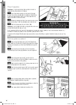
Slide the hinge guides (B1 & B2) onto the rear
frame stiles. The brackets should be positioned
outwards, with the double holed half uppermost (see
diagram).
4.2
C1
C2
C3
Permanent top stop
Slide all the way up to the factory–fitted
permanent top stops.
4.3
Do not replace the plastic end tips at this
stage (see later at step 6.5).
4.4
3 Section Operating Heights
Millimetres
Feet & Inches
Notes
2133 to 2286
7’ 0” to 7’ 6”
Fit additional top stops
2286 to 2415
7’ 6” to 7’ 11”
Do not fit additional top stops
2415 to 2565
7’ 11” to 8’ 5”
Fit additional top stops
2565 to 2705
8’ 5” to 8’ 10
1
/
2
”
Do not fit additional top stops
2705 to 2845
8’ 10
1
/
2
” to 9’ 4”
Fit additional top stops
2845 to 3000
9’ 4” to 9’ 10”
Do not fit additional top stops
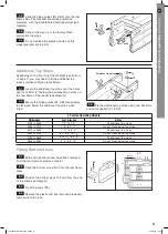
Additional Top Stops
Depending on the floor to loft floor height (see bottom
of page 1), you may need to fit the additional top
stops provided (C2) (see table below).
Locate the additional top stops over the holes
approx 150mm (6") below the permanent top stops on
the rear frame of the ladder (see diagram).
Ensure the hinge guides (B1 & B2) are already
in place and below the additional top stops when
fitted.
5.2
5.1
Fix the additional top stops using two M4 bolts
and nuts supplied (C1 & C3).
5.3
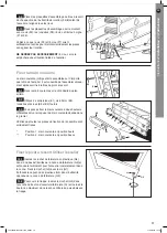
Fitting Bottom Stops
Both end tips should now have been removed
from the rear frame at previous step 4.1.
Slide the bottom stops (D1) onto the rear frame
stiles.
Position the bottom stops 150 mm from the end
of the stiles (see diagram).
Fix with screws (D2).
Replace the plastic end tips removed previously
and secure with studs.
6.2
6.1
6.5
6.4
6.3
D1
D2
Right
side
Left
side
150 mm
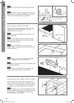
Adapting the trapdoor
The loft ladder is suitable for a loft opening let flush
into the ceiling, having a hinged trapdoor opening
downwards, with a suitable fastener to keep the hatch
firmly shut. If the trapdoor does not hinge downwards,
or is not hinged at all, you will need to adapt or replace
it so that it does. The parts needed are enclosed.
Hanging the trapdoor
G5
Minimum
of 1" (26mm)
Use the existing cover as a template to cut
out the new piece, ensuring a slightly loose fit all
round, (3mm (
1
/
8
”) maximum). Your DIY store may be
able to do this for you.
1.2
Remove the existing trapdoor and hinges.
Prise off any support battens so that the four faces of
the loft trap frame are flat.
1.3
Screw hinges (G5) to one edge of the
trapdoor using 20mm (
3
/
4
”) wood screws
1.4
For extra performance fill the screw holes with
wood glue.
1.5
Offer up the hinges to the face of the frame on
the same end as you intend setting the ladder, and fix.
1.6
Ensure that there is at least 26mm (1”)
clearance between the top face of the trapdoor and
the top edge of the framework.
1.7
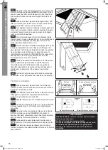
Fitting the Twist Catch
A1
A2
A4
A3
Find the mid-point of the trapdoor edge
opposite to the hinged side. This will give you your
centre line (see diagram). Mark with a pencil.
2.1
With the trapdoor fully closed measure
exactly 26mm (1”) in from the edge of the frame and
mark with a pencil.
2.2
Drill a 13mm (½”) hole in the centre and sand
off any rough edges.
2.3
Pass the catch operator (A1) through the
trapdoor hole from the underside such that the
position pointer points towards the trapdoor edge.
2.4
Place the travel stop ring (A2) over the
operator such that the securing tag is at 45 degrees
to the trapdoor centre line.
2.5
Place the catch lever (A3) over the operator
and locate into the operator groove such that the
lever points towards the trapdoor near edge and fully
locates within the travel stop ring (A2).
2.6
Trapdoor
Trapdoor Centre Line
26mm
ø13mm
Hole centre to
inside face of
hatch frame
Stowed Requirements
Deployed Requirements
68°- 80°
* At handrail low position - 710mm (28”)
At handrail top position - 965mm (38”)
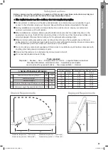
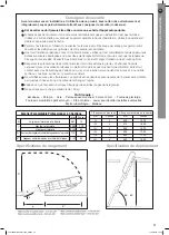
Safety Instructions
Before commencing the installation or operation of this product, read these instructions carefully and
completely, noting in particular the instructions regarding safety (below).
This ladder should never be used as a free standing leaning ladder.
Do not attempt to climb your loft ladder until installation is complete. Use a second ladder to gain
access to the loft while carrying out the work. Ensure that this is stable and suitable for the task.
During installation and operation, follow all instructions step by step to ensure your safety and
optimum performance of the loft ladder.
When installation is complete, before using the ladder make sure that it is pulled fully down to the
appropriate top stops, that both feet are resting firmly on the floor and that the locking catches are
properly engaged. Observe the instructions for the optimum safe working angle.
Observe normal safety precautions when working in the loft space. Place weight only on the main
ceiling joists. Do not drill above head height. Avoid contact with electrical wiring. Ensure someone else
is on the premises and knows where you are in case of an accident.
Do not modify any component supplied with this product or substitute any loft ladder component with
anything other than genuine replacement parts.
E
Do not exceed maximum load of 150kg.
nsure that the ladder is not obstructed by items stowed in the loft.
3 Section Professional Loft Ladder
mm Inches
B
Minimum Hatch Opening (Width)
381
15
C
Maximum Height
3000
118
Minimum Height
2133
84
D* Minimum Stowing Height Required In Loft
710
28
E** Minimum Length Required Behind Hatch
1120
44
C
** At handrail low position - 1120mm (44”)
At handrail top position - 1370mm (54”)
Fixing the Location Bracket
When turned to the correct position, the catch lever
will engage in the location bracket to hold the
trapdoor shut. Fix as follows:
Position the catch location bracket (A5) as
shown in diagram, along the horizontal line.
3.4
Thickness of Door
Thickness
of Door +9mm
Thickness
of Door +9mm
A6
A5
Mark a vertical line on the inside of the
trapdoor frame corresponding with the centre line of
the trapdoor catch.
3.3
Measure the thickness of the trapdoor, add
9mm (
3
/
8
”) to this.
3.1
On the closing edge of the hatch opening,
draw a line this distance up from the bottom edge
parallel with the opening.
3.2
Match up the indent mark on the bracket with
the vertical centre line.
3.5
Make guide holes with the bradawl and fix,
using two 20mm wood screws supplied (A6).
3.6
Secure the travel stop ring (A2) using screw
(A7).
2.7
Secure the catch assembly with M12 nut (A4)
ensuring the nut is tightened sufficiently to allow the
catch to rotate freely without any looseness.
2.8
Rear
Frame
Front
Fram
e
Assembling the Ladder and Fittings
N.B. The long sides of the ladder are known as the
‘stiles’. Each complete section of the ladder is known
as a ‘frame’. For correct identification, the front frame
of the ladder can be identified by its rounded feet.
Carefully push out the studs (lightly tap with a
hammer if necessary) and remove the plastic end tips
from the bottom of the REAR frame of the ladder,
noting which way round they go.
4.1
A1
A4
A7
A3
A2
A3
A2
45°
F (Floor Thickness)
A (Minimum Hatch Opening Length)
mm
Inches
mm
Inches
76.0
3
400.0
15.75
102.0
4
412.0
16.25
127.0
5
425.0
16.75
153.0
6
438.0
17.25
178.0
7
450.0
17.75
203.0
8
463.0
18.25
If a new trapdoor is required, its thickness
must not exceed 20mm (3/4”). Consider the weight of
the trapdoor and the security of the hinge screws.
Chipboard and MDF may not be suitable.
1.1
Stepladder • Bradawl • Saw • Drill plus 13mm & 2mm bit • Large flat bladed screwdriver
Crosshead Screwdriver: small and medium • Adjustable spanner/pliers
Lever to prise off any support battens • Tape measure/Ruler • Hammer
D
*
E**
A
B
F
F4
Position the ladder in its fully stowed (closed)
position carefully in the loft.
Remove the stud and plastic top tip from the
top of the required side stile of the rear ladder frame
and discard.
In their place fit Pivot Tip (F4).
8.8
8.7
8.6
F2
F3
F1
F3
F3
Place the spring housing (F1) in position over
the holes ensuring the arm points AWAY from the loft
opening (with slot in cover on the left-hand side).
Fix the spring housing to the loft floor with 4 x
20mm screws (F3) through the 4 inner holes.
Place the housing cover (F2) over the spring
housing and fix down using 2 x 20mm (F3) screws
through the 2 remaining outer holes.
8.5
8.4
8.3
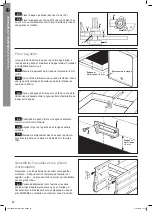
Installing the Power Pivot System
Position the template cut from the rear of the
header card against either the left or right hand hinge
guide bracket (depending on which chosen side the
power pivot system is to be fitted).
Using a bradawl mark the 6 applicable holes
through the template on to the loft floor.
8.2
8.1
For Right
Hand Fixing
For Left
Hand Fixing
WARNING:
Do Not stand on the ladder to do this. Either using a
second ladder, or from inside the loft space, secure
the hinges using six 35mm screws supplied.
B3
B1
B2
If flooring material covers the top edge of the loft hatch frame ensure that it is completely stable and if necessary
use longer screws to penetrate the frame itself.
The ladder should now be free to swing from the hinges and slide freely up and down the guides.
Installing the Ladder
N.B.
The ladder should be installed on the same side
of the trap as the trapdoor hinges.
With the ladder preferably centred in the
opening, and the trapdoor hanging down, locate the
hinge guide bracket arms (B1 & B2) on the top edge
of the loft hatch frame (see diagram).
Make guide holes with the bradawl then pre
drill pilot holes (2mm diameter) for all screws.
Fix using 35mm screws (B3).
N.B.
the bracket arms with two screw holes should be
on top.
7.3
7.2
7.1
E2
E1
E2
E1
G6
F5
F8 F7 F6
F4
F6
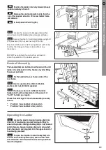
Handrail Assembly
The handrail (G6) can be fitted to either side of the loft
ladder. It is advisable to fit the handle only after fitting
the power pivot arm.
Fix the handrail to your chosen side of the
rear frame.
Use 3 x spacers (E1), 60mm bolts (E2),
washers and nuts (E3 & E4) supplied.
You have a choice of 2 different handrail
heights which will be dependent on the amount of
“in-loft” handrail you require.
Check that all fixings for the whole assembly are fully
secure.
9.3
9.2
9.1
Locate the power arm linkage plates either
side of pivot tip (F4)/ladder stile and align all holes.
Secure the stile to the linkage plates using bolt
(F5), washers (F6), nut and nut cap (F7 & F8).
Ensure bolt (F5) and nut (F7) are tightened sufficiently
to allow the linkage to freely rotate without any
looseness.
DO NOT over-tighten the nut as this will restrict
smooth operation of the ladder system.
8.10
8.9
G3
A1
G2
G3
1*
1*
1*
2**
2**
2**
*
Position 1 fixes handrail in top position
** Position 2 fixes handrail in low position
G6
E1
E2
E2
E1
E3
E4
IMPORTANT
DO NOT attempt to climb your loft ladder until installation is
complete and the ladder is pulled down to appropriate top
stops. Then ensure that the locking catches are engaged.
TWIST C
ATCH
ASSEMBL
Y
HANDRAIL ASSEMBL
Y
BO
TTOM STOPS
ADDITIONAL TOP
STOPS
HINGE
GUIDE ASSEMBL
Y
A1
Catch Operator
. . . . . . . . . . . .
x1
A2
Travel Stop Ring
. . . . . . . . . . .
x1
A3
Catch Lever
. . . . . . . . . . . . . . .
x1
A4
Nut (M12)
. . . . . . . . . . . . . . . . .
x1
A5
Location Bracket
. . . . . . . . . .
x1
A6
Screw (20mm)
. . . . . . . . . . . .
x2
A7
Screw (12mm)
. . . . . . . . . . . .
x1
C1
Top Stop Bolt (M4 x 8mm)
.
x2
C2
Additional Top Stop
. . . . . . . .
x2
C3
Locking Nut (M4)
. . . . . . . . . .
x2
A
B
D
E
F1
Power Pivot Unit
. . . . . . . . . .
x1
F2
Housing Cover
. . . . . . . . . . . .
x1
F3
Screw (20mm)
. . . . . . . . . . . .
x6
F4
Pivot Tip
. . . . . . . . . . . . . . . . . .
x1
F5
Bolt (M6 x 40mm)
. . . . . . . .
x1
F6
Plastic Washer
. . . . . . . . . . . .
x2
F7
Locking Nut (M6)
. . . . . . . . . .
x1
F8
Nut Cap
. . . . . . . . . . . . . . . . . . .
x1
F9
Card Template
. . . . . . . . . . . . .
x1
(on back of header card)
PIVO
T ASSEMBL
Y
E1
Handrail Spacer
. . . . . . . . . . .
x3
E2
Bolt (M5 x 60mm)
. . . . . . . .
x3
E3
Washer (
ø
25mm)
. . . . . . . . .
x3
E4
Locking Nut (M5)
. . . . . . . . .
x3
D1
Bottom Stop
. . . . . . . . . . . . . . .
x2
D2
Screw (12mm)
. . . . . . . . . . . .
x4
B1
Hinge Guide (left)
. . . . . . . . . .
x1
B2
Hinge Guide (right)
. . . . . . . .
x1
B3
Screw (35mm)
. . . . . . . . . . . .
x6
F
B2
B3
C1
C2
G2
C3
D2
G1
G6
G5
D1
G6
C
E1
E2
E2
E1
E3
F2
F5
F6
F3
F1
F8
F7
F6
E4
G
G1
3-Section Loft Ladder
. . . . .
x1
G2
Stowing Pole
. . . . . . . . . . . . .
x1
G3
Plastic Stowing Hook/Key
.
x1
G4
End Plug
. . . . . . . . . . . . . . . . . .
x1
(Trapdoor not provided)
G5
Trapdoor Hinges
. . . . . . . . . .
x2
Screws (20mm
. . . . . . .
x8
G6
Handrail
. . . . . . . . . . . . . . . . . . .
x1
G7
Self-tapping screw
. . . . . . . .
x1
F3
F4
A2
A4
A5
A6
A3
A1
G4
A7
B1
Additional
Top stops
Fitted
No Additional
Top stops
Fitted
B
A
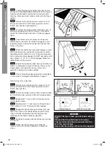
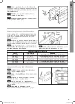
Operating the Ladder
Locate the plastic stowing hook/key (G3) into
one end of the stowing pole (G2) and push firmly to
ensure the plastic stowing hook/key (G3) is fully located
within the pole. Secure hook/key (G3) with screw (G7).
Push the plastic end plug (G4) into the opposite end of
the stowing pole (G2).
To open the trapdoor locate the key (G3) into
the slot in the catch operator (A1) and turn the catch
anti-clockwise until it reaches the travel stop and then
lower the trapdoor.
10.2
10.1
Stowing the Ladder
Retract both right-hand side catches ‘C’ & ‘D’
(blue) and rotate both catch levers upwards into the
locked open position.
To stow the ladder, retract catch ‘A’ (black), slide
the front frame fully upwards until catch engages again.
Repeat step 11.2 for catch ‘B’ (black) and the
middle ladder frame.
Engage the plastic stowing hook/key (E3) over
and at the centre of the REAR ladder section bottom
rung and whilst maintaining the stowing pole near
vertical push the ladder vertically upwards.
Continue to slowly push the ladder up and fully
into the loft.
11.6
11.5
11.3
11.2
11.1
G3
G7
Catches
‘C’ & ‘D’
Released/engaged
Retracted/locked open
WARNING:
DO NOT attempt to climb your loft ladder until you
have:
Checked that it is pulled down to the stops.
Fully read all safety labels and ensured that it is
set at the correct angle.
Ensure that the locking catches are fully engaged.
Locate the stowing hook/key (E3) over and at
the centre of the REAR ladder section bottom rung and
steadily pull the ladder outward and downward until
both top stops reach and make contact with the hinge
guides.
10.3
To extend the ladder, retract left-hand catch ‘A’
(black) while supporting the front frame of the ladder.
Lower the frame slowly until catch ‘A’ (black) engages
again.
Then retract catch ‘B’ (black) and lower the
middle frame until catch ‘B’ (black) is engaged in your
required position. Extend the ladder until the feet rest
firmly on the floor.
When the ladder has been fully deployed, rotate
both right-hand side catch levers downward to unlock
and release both catches ‘C’ and ‘D’ (blue) and ensure
both catches are fully engaged. Do NOT use ladder with
any catches (‘A’, ‘B’, ‘C’ or ‘D’) disengaged. Read the
safety labels on the product.
10.5
10.6
Ensure the ladder is pulled down so that the top
stops or additional top stops if fitted rest firmly on the
hinge guides. This supports the top section and
prevents it sliding down when climbed.
Check the ladder angle against the safety label
or refer back to deployed requirements on page 1.
10.9
10.8
Retract both right-hand side catches ‘C’ & ‘D’
(blue) and rotate both catch levers upwards into the
locked open position (see diagram).
10.4
10.7
C
D
Finally, use the stowing pole to raise the
trapdoor and turn the catch operator clockwise to
close.
11.7
Reverse step 11.1 and ensure both right-hand
side catches ‘C’ and ‘D’ (blue) are fully engaged.
11.4
CSK)
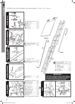
Please check you have all components listed (tick boxes)
LF37093 MacAllister.indd 4
28/04/2016 14:52
05
Installation
and
operating
instructions
Tools required:
B1
B2
Slide the hinge guides (B1 & B2) onto the rear
frame stiles. The brackets should be positioned
outwards, with the double holed half uppermost (see
diagram).
4.2
C1
C2
C3
Permanent top stop
Slide all the way up to the factory–fitted
permanent top stops.
4.3
Do not replace the plastic end tips at this
stage (see later at step 6.5).
4.4
3 Section Operating Heights
Millimetres
Feet & Inches
Notes
2133 to 2286
7’ 0” to 7’ 6”
Fit additional top stops
2286 to 2415
7’ 6” to 7’ 11”
Do not fit additional top stops
2415 to 2565
7’ 11” to 8’ 5”
Fit additional top stops
2565 to 2705
8’ 5” to 8’ 10
1
/
2
”
Do not fit additional top stops
2705 to 2845
8’ 10
1
/
2
” to 9’ 4”
Fit additional top stops
2845 to 3000
9’ 4” to 9’ 10”
Do not fit additional top stops
Additional Top Stops
Depending on the floor to loft floor height (see bottom
of page 1), you may need to fit the additional top
stops provided (C2) (see table below).
Locate the additional top stops over the holes
approx 150mm (6") below the permanent top stops on
the rear frame of the ladder (see diagram).
Ensure the hinge guides (B1 & B2) are already
in place and below the additional top stops when
fitted.
5.2
5.1
Fix the additional top stops using two M4 bolts
and nuts supplied (C1 & C3).
5.3
Fitting Bottom Stops
Both end tips should now have been removed
from the rear frame at previous step 4.1.
Slide the bottom stops (D1) onto the rear frame
stiles.
Position the bottom stops 150 mm from the end
of the stiles (see diagram).
Fix with screws (D2).
Replace the plastic end tips removed previously
and secure with studs.
6.2
6.1
6.5
6.4
6.3
D1
D2
Right
side
Left
side
150 mm
Adapting the trapdoor
The loft ladder is suitable for a loft opening flush with
the ceiling, having a hinged trapdoor opening
downwards, with a suitable fastener to keep the hatch
firmly shut. If the trapdoor does not hinge downwards,
or is not hinged at all, you will need to adapt or replace
it so that it does. The parts needed are enclosed.
Hanging the trapdoor
G5
Minimum
of 1" (26mm)
Use the existing cover as a template to cut
out the new piece, ensuring a slightly loose fit all
round, (3mm (
1
/
8
”) maximum). Your DIY store may be
able to do this for you.
1.2
Remove the existing trapdoor and hinges.
Prise off any support battens so that the four faces of
the loft trap frame are flat.
1.3
Screw hinges (G5) to one edge of the
trapdoor using 20mm (
3
/
4
”) wood screws.
1.4
For extra performance fill the screw holes with
wood glue.
1.5
Offer up the hinges to the face of the frame on
the same end as you intend setting the ladder, and fix.
1.6
Ensure that there is at least 26mm (1”)
clearance between the top face of the trapdoor and
the top edge of the framework.
1.7
Fitting the Twist Catch
A1
A2
A4
A3
Find the mid-point of the trapdoor edge
opposite to the hinged side. This will give you your
centre line (see diagram). Mark with a pencil.
2.1
With the trapdoor fully closed measure
exactly 26mm (1”) in from the edge of the frame and
mark with a pencil.
2.2
Drill a 13mm (½”) hole in the centre and sand
off any rough edges.
2.3
Pass the catch operator (A1) through the
trapdoor hole from the underside such that the
position pointer points towards the trapdoor edge.
2.4
Place the travel stop ring (A2) over the
operator such that the securing tag is at 45 degrees
to the trapdoor centre line.
2.5
Place the catch lever (A3) over the operator
and locate into the operator groove such that the
lever points towards the trapdoor near edge and fully
locates within the travel stop ring (A2).
2.6
Trapdoor
Trapdoor Centre Line
26mm
ø13mm
Hole centre to
inside face of
hatch frame
Stowed Requirements
Deployed Requirements
68°- 80°
* At handrail low position - 710mm (28”)
At handrail top position - 965mm (38”)
Safety Instructions
Before commencing the installation or operation of this product, read these instructions carefully and
completely, noting in particular the instructions regarding safety (below).
This ladder should never be used as a free standing leaning ladder.
Do not attempt to climb your loft ladder until installation is complete. Use a second ladder to gain
access to the loft while carrying out the work. Ensure that this is stable and suitable for the task.
During installation and operation, follow all instructions step by step to ensure your safety and
optimum performance of the loft ladder.
When installation is complete, before using the ladder make sure that it is pulled fully down to the
appropriate top stops, that both feet are resting firmly on the floor and that the locking catches are
properly engaged. Observe the instructions for the optimum safe working angle.
Observe normal safety precautions when working in the loft space. Place weight only on the main
ceiling joists. Do not drill above head height. Avoid contact with electrical wiring. Ensure someone else
is on the premises and knows where you are in case of an accident.
Do not modify any component supplied with this product or substitute any loft ladder component with
anything other than genuine replacement parts.
E
Do not exceed maximum load of 150kg.
nsure that the ladder is not obstructed by items stowed in the loft.
3 Section Professional Loft Ladder
mm Inches
B
Minimum Hatch Opening (Width)
381
15
C
Maximum Height
3000
118
Minimum Height
2133
84
D* Minimum Stowing Height Required In Loft
710
28
E** Minimum Length Required Behind Hatch
1120
44
C
** At handrail low position - 1120mm (44”)
At handrail top position - 1370mm (54”)
Fixing the Location Bracket
When turned to the correct position, the catch lever
will engage in the location bracket to hold the
trapdoor shut. Fix as follows:
Position the catch location bracket (A5) as
shown in diagram, along the horizontal line.
3.4
Thickness of Door
Thickness
of Door +9mm
Thickness
of Door +9mm
A6
A5
Mark a vertical line on the inside of the
trapdoor frame corresponding with the centre line of
the trapdoor catch.
3.3
Measure the thickness of the trapdoor, add
9mm (
3
/
8
”) to this.
3.1
On the closing edge of the hatch opening,
draw a line this distance up from the bottom edge
parallel with the opening.
3.2
Match up the indent mark on the bracket with
the vertical centre line.
3.5
Make guide holes with the bradawl and fix,
using two 20mm wood screws supplied (A6).
3.6
Secure the travel stop ring (A2) using screw
(A7).
2.7
Secure the catch assembly with M12 nut (A4)
ensuring the nut is tightened sufficiently to allow the
catch to rotate freely without any looseness.
2.8
Rear
Frame
Front
Fram
e
Assembling the Ladder and Fittings
N.B. The long sides of the ladder are known as the
‘stiles’. Each complete section of the ladder is known
as a ‘frame’. For correct identification, the front frame
of the ladder can be identified by its rounded feet.
Carefully push out the studs (lightly tap with a
hammer if necessary) and remove the plastic end tips
from the bottom of the REAR frame of the ladder,
noting which way round they go.
4.1
A1
A4
A7
A3
A2
A3
A2
45°
F (Floor Thickness)
A (Minimum Hatch Opening Length)
mm
Inches
mm
Inches
76.0
3
400.0
15.75
102.0
4
412.0
16.25
127.0
5
425.0
16.75
153.0
6
438.0
17.25
178.0
7
450.0
17.75
203.0
8
463.0
18.25
If a new trapdoor is required, its thickness
must not exceed 20mm (3/4”). Consider the weight of
the trapdoor and the security of the hinge screws.
Chipboard and MDF may not be suitable.
1.1
Stepladder • Bradawl • Saw • Drill plus 13mm & 2mm bit • Large flat bladed screwdriver
Crosshead Screwdriver: small and medium • Adjustable spanner/pliers
Lever to prise off any support battens • Tape measure/Ruler • Hammer
D
*
E**
A
B
F
F4
Position the ladder in its fully stowed (closed)
position carefully in the loft.
Remove the stud and plastic top tip from the
top of the required side stile of the rear ladder frame
and discard.
In their place fit Pivot Tip (F4).
8.8
8.7
8.6
F2
F3
F1
F3
F3
Place the spring housing (F1) in position over
the holes ensuring the arm points AWAY from the loft
opening (with slot in cover on the left-hand side).
Fix the spring housing to the loft floor with 4 x
20mm screws (F3) through the 4 inner holes.
Place the housing cover (F2) over the spring
housing and fix down using 2 x 20mm (F3) screws
through the 2 remaining outer holes.
8.5
8.4
8.3
Installing the Power Pivot System
Position the template cut from the rear of the
header card against either the left or right hand hinge
guide bracket (depending on which chosen side the
power pivot system is to be fitted).
Using a bradawl mark the 6 applicable holes
through the template on to the loft floor.
8.2
8.1
For Right
Hand Fixing
For Left
Hand Fixing
WARNING:
Do Not stand on the ladder to do this. Either using a
second ladder, or from inside the loft space, secure
the hinges using six 35mm screws supplied.
B3
B1
B2
If flooring material covers the top edge of the loft hatch frame ensure that it is completely stable and if necessary
use longer screws to penetrate the frame itself.
The ladder should now be free to swing from the hinges and slide freely up and down the guides.
Installing the Ladder
N.B.
The ladder should be installed on the same side
of the trap as the trapdoor hinges.
With the ladder preferably centred in the
opening, and the trapdoor hanging down, locate the
hinge guide bracket arms (B1 & B2) on the top edge
of the loft hatch frame (see diagram).
Make guide holes with the bradawl then pre
drill pilot holes (2mm diameter) for all screws.
Fix using 35mm screws (B3).
N.B.
the bracket arms with two screw holes should be
on top.
7.3
7.2
7.1
E2
E1
E2
E1
G6
F5
F8 F7 F6
F4
F6
Handrail Assembly
The handrail (G6) can be fitted to either side of the loft
ladder. It is advisable to fit the handle only after fitting
the power pivot arm.
Fix the handrail to your chosen side of the
rear frame.
Use 3 x spacers (E1), 60mm bolts (E2),
washers and nuts (E3 & E4) supplied.
You have a choice of 2 different handrail
heights which will be dependent on the amount of
“in-loft” handrail you require.
Check that all fixings for the whole assembly are fully
secure.
9.3
9.2
9.1
Locate the power arm linkage plates either
side of pivot tip (F4)/ladder stile and align all holes.
Secure the stile to the linkage plates using bolt
(F5), washers (F6), nut and nut cap (F7 & F8).
Ensure bolt (F5) and nut (F7) are tightened sufficiently
to allow the linkage to freely rotate without any
looseness.
DO NOT over-tighten the nut as this will restrict
smooth operation of the ladder system.
8.10
8.9
G3
A1
G2
G3
1*
1*
1*
2**
2**
2**
*
Position 1 fixes handrail in top position
** Position 2 fixes handrail in low position
G6
E1
E2
E2
E1
E3
E4
IMPORTANT
DO NOT attempt to climb your loft ladder until installation is
complete and the ladder is pulled down to appropriate top
stops. Then ensure that the locking catches are engaged.
TWIST
CA
TCH
ASSEMBL
Y
HANDRAIL
ASSEMBL
Y
BO
TTOM
STOPS
ADDITIONAL
TOP
STOPS
HINGE
GUIDE
ASSEMBL
Y
A1
Catch Operator
. . . . . . . . . . . .
x1
A2
Travel Stop Ring
. . . . . . . . . . .
x1
A3
Catch Lever
. . . . . . . . . . . . . . .
x1
A4
Nut (M12)
. . . . . . . . . . . . . . . . .
x1
A5
Location Bracket
. . . . . . . . . .
x1
A6
Screw (20mm)
. . . . . . . . . . . .
x2
A7
Screw (12mm)
. . . . . . . . . . . .
x1
C1
Top Stop Bolt (M4 x 8mm)
.
x2
C2
Additional Top Stop
. . . . . . . .
x2
C3
Locking Nut (M4)
. . . . . . . . . .
x2
A
B
D
E
F1
Power Pivot Unit
. . . . . . . . . .
x1
F2
Housing Cover
. . . . . . . . . . . .
x1
F3
Screw (20mm)
. . . . . . . . . . . .
x6
F4
Pivot Tip
. . . . . . . . . . . . . . . . . .
x1
F5
Bolt (M6 x 40mm)
. . . . . . . .
x1
F6
Plastic Washer
. . . . . . . . . . . .
x2
F7
Locking Nut (M6)
. . . . . . . . . .
x1
F8
Nut Cap
. . . . . . . . . . . . . . . . . . .
x1
F9
Card Template
. . . . . . . . . . . . .
x1
(on back of header card)
PIVO
T
ASSEMBL
Y
E1
Handrail Spacer
. . . . . . . . . . .
x3
E2
Bolt (M5 x 60mm)
. . . . . . . .
x3
E3
Washer (
ø
25mm)
. . . . . . . . .
x3
E4
Locking Nut (M5)
. . . . . . . . .
x3
D1
Bottom Stop
. . . . . . . . . . . . . . .
x2
D2
Screw (12mm)
. . . . . . . . . . . .
x4
B1
Hinge Guide (left)
. . . . . . . . . .
x1
B2
Hinge Guide (right)
. . . . . . . .
x1
B3
Screw (35mm)
. . . . . . . . . . . .
x6
F
B2
B3
C1
C2
G2
C3
D2
G1
G6
G5
D1
G6
C
E1
E2
E2
E1
E3
F2
F5
F6
F3
F1
F8
F7
F6
E4
G
G1
3-Section Loft Ladder
. . . . .
x1
G2
Stowing Pole
. . . . . . . . . . . . .
x1
G3
Plastic Stowing Hook/Key
.
x1
G4
End Plug
. . . . . . . . . . . . . . . . . .
x1
(Trapdoor not provided)
G5
Trapdoor Hinges
. . . . . . . . . .
x2
Screws (20mm
. . . . . . .
x8
G6
Handrail
. . . . . . . . . . . . . . . . . . .
x1
G7
Self-tapping screw
. . . . . . . .
x1
F3
F4
A2
A4
A5
A6
A3
A1
G4
A7
B1
Additional
Top stops
Fitted
No Additional
Top stops
Fitted
B
A
Operating the Ladder
Locate the plastic stowing hook/key (G3) into
one end of the stowing pole (G2) and push firmly to
ensure the plastic stowing hook/key (G3) is fully located
within the pole. Secure hook/key (G3) with screw (G7).
Push the plastic end plug (G4) into the opposite end of
the stowing pole (G2).
To open the trapdoor locate the key (G3) into
the slot in the catch operator (A1) and turn the catch
anti-clockwise until it reaches the travel stop and then
lower the trapdoor.
10.2
10.1
Stowing the Ladder
Retract both right-hand side catches ‘C’ & ‘D’
(blue) and rotate both catch levers upwards into the
locked open position.
To stow the ladder, retract catch ‘A’ (black), slide
the front frame fully upwards until catch engages again.
Repeat step 11.2 for catch ‘B’ (black) and the
middle ladder frame.
Engage the plastic stowing hook/key (E3) over
and at the centre of the REAR ladder section bottom
rung and whilst maintaining the stowing pole near
vertical push the ladder vertically upwards.
Continue to slowly push the ladder up and fully
into the loft.
11.6
11.5
11.3
11.2
11.1
G3
G7
Catches
‘C’ & ‘D’
Released/engaged
Retracted/locked open
WARNING:
DO NOT attempt to climb your loft ladder until you
have:
Checked that it is pulled down to the stops.
Fully read all safety labels and ensured that it is
set at the correct angle.
Ensure that the locking catches are fully engaged.
Locate the stowing hook/key (E3) over and at
the centre of the REAR ladder section bottom rung and
steadily pull the ladder outward and downward until
both top stops reach and make contact with the hinge
guides.
10.3
To extend the ladder, retract left-hand catch ‘A’
(black) while supporting the front frame of the ladder.
Lower the frame slowly until catch ‘A’ (black) engages
again.
Then retract catch ‘B’ (black) and lower the
middle frame until catch ‘B’ (black) is engaged in your
required position. Extend the ladder until the feet rest
firmly on the floor.
When the ladder has been fully deployed, rotate
both right-hand side catch levers downward to unlock
and release both catches ‘C’ and ‘D’ (blue) and ensure
both catches are fully engaged. Do NOT use ladder with
any catches (‘A’, ‘B’, ‘C’ or ‘D’) disengaged. Read the
safety labels on the product.
10.5
10.6
Ensure the ladder is pulled down so that the top
stops or additional top stops if fitted rest firmly on the
hinge guides. This supports the top section and
prevents it sliding down when climbed.
Check the ladder angle against the safety label
or refer back to deployed requirements on page 1.
10.9
10.8
Retract both right-hand side catches ‘C’ & ‘D’
(blue) and rotate both catch levers upwards into the
locked open position (see diagram).
10.4
10.7
C
D
Finally, use the stowing pole to raise the
trapdoor and turn the catch operator clockwise to
close.
11.7
Reverse step 11.1 and ensure both right-hand
side catches ‘C’ and ‘D’ (blue) are fully engaged.
11.4
CSK)
Please check you have all components listed (tick boxes)
28/04/2016 14:52
LF37093 MacAllister 1219_PRINT
7
11/12/2019 14:18


