Mac Medical SS Series Instruction Manual Download Page 15

Instruction Manual

MAN-004

15

www.macmedical.com

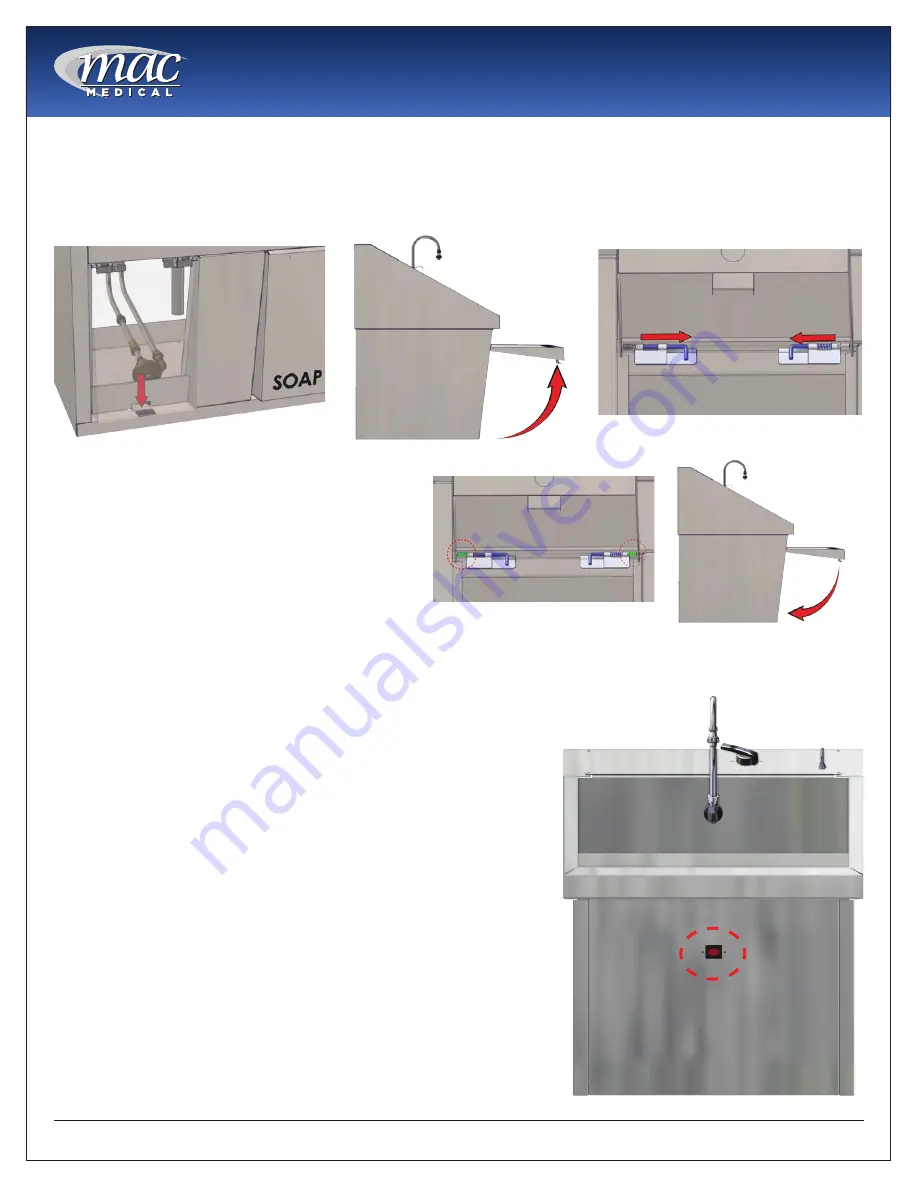
Plumbing Access ( Manual Knee Operated Sinks Only)

1.  Open the knee panel door by depressing the latch at the bottom of the panel door (Fig. 24).
2.  Swing the door fully open to access the hinges (Fig. 25).
3. 

Push the hinge pins inward to release the door from the hinges (Fig. 26).

Infrared Controls (for Infrared Self-Activated Sinks only)

Installation 

The sinks are supplied with a 24V power transformer(s) that connects 

to a standard duplex outlet (110/120V outlet required).   
Single basin sinks have one sensor, dual basin sinks have two sensors 

(one for each basin) and triple basin sinks have three sensors (one for 

each basin).
1. 

Plug the transformer(s) into the outlet. 

2. 

A red LED will flash in the sensor window (Fig. 29 - circled in red).  

A. 

Important:

 Do not interrupt the sensor beam until the light 

turns off.

Operation 

The sensors are pre-set and equipped with a logic board. The sensors 

determines the range during initialization period (The time after initial 

power until the light turns off is approximately 5 minutes). The range is 

approximately 12-14” in front of the sensor and is 25 degrees at peak.

During the initialization period, the sensors allow for fixed objects that 

may be within the sensors’ range. The sensors are equipped with a 2 

second on/off delay, and no-time-out feature. This prevents the sink 

from turning on when walking past at a normal pace and no-time-

out allows for an uninterrupted scrub.

4.  To re-attach the door, push in the hinge pins 

and fit the top corners of the knee panel 

door onto the left and right hinge leaves (Fig. 

27 - circled in red). When the door is refitted, 

release the hinge pins to secure the door to 

the sink. 

5.  The knee panel door should rotate freely on 

its hinges. Rotate the door back down on its 

bottom latch to close it (Fig. 28).

Fig. 24:

 Push down knee panel door latch

Fig. 25:

 Door in fully opened position

Fig. 26:

 Push hinges inward

Fig. 27: Left - right hinge leaves

Fig. 28:

 Door should rotate freely on hinges

Fig. 29: Location of infrared sensor

Summary of Contents for SS Series

Page 1: ...instructions and safety information in this manual before operating this product MAN 004 Rev G 02 2019 2019 MAC Medical Inc SS Series Surgical Scrub Sinks Installation Operation Maintenance Cleaning OSHPD Pre Approved SS32 Model SS64 Model SS96 Model C ...

Page 2: ...ng Specifications SS32 Single Basin 9 Recommended Mounting Specifications SS64 Double Basin 10 Recommended Mounting Specifications SS96 Triple Basin 11 Connect Drain Pipe to Drain and Plumbing to Water Lines 12 Plumbing Install Instructions 12 Preventative Maintenance 13 Troubleshooting 13 Replacement Parts for Manual Knee Operated and Infrared Self Activated Sink Plumbing 14 Plumbing Access Manua...

Page 3: ... with this equipment The use of inexperienced unqualified persons to service the equipment or the installation of unauthorized parts could cause serious personal injury or result in costly damage Always unplug power cord from power source prior to attempting any repairs or servicing WARNING Burn Hazard DO NOT CHANGE temperature settings on thermostatic mixing valve unless you are a trained mechani...

Page 4: ...equirements for sinks with optional infrared sensor operations a 120 Volt 60 Hz single phase 3 0 amp GFIC protected electrical outlet by others b 220 VAC 60 Hz single phase 1 5 amp c to be installed per local building codes 5 Sink Weight a Single basin 130 lbs b Double basin 230 lbs c Triple basin 320 lbs 6 Sink Certifications a UL and cUL certified b California OSHPD pre approved when mounted on ...

Page 5: ...ction of excessive or insufficient flow rates Switch Ratings Max Resistive Load Switch Timer Controller Maintenance Accumulation of foreign debris should periodically be removed from these switches Occasional wipe down cleaning when excessive contamination is present is all that is normally required To Clean Remove unit from system and disassemble as shown below Clean all parts reassemble and rein...

Page 6: ...Instruction Manual MAN 004 6 www macmedical com Sink Dimensions SS32 SS64 SS96 Models Fig 2 SS32 single basin Fig 3 SS64 Dual Basin Fig 4 SS96 Triple Basin ...

Page 7: ...nded mounting specifications for Z brackets shown in Fig 13 SS32 Fig 16 SS64 and Fig 19 SS96 on page 9 through page 11 B IMPORTANT For wall mounted units the wall structure must be capable of supporting the load C Optional wall mounting systems in wall chair carrier and pedestal style and their mounting specifications shown in Fig 15 part S0001 for sink SS32 Fig 18 part S0002 for sink SS64 and Fig...

Page 8: ...out item 1 through the small hole at the top of the sink Fig 9 The nut item 2 should rest on top of the sink 3 Re install the bushing onto the spout from inside the cabinet Fig 10 4 Attach the soap tubing to the spout and soap pump circled in red as shown in Fig 11 and Fig 12 To Operate the Soap Pump press the soap spout down repeatedly to start the flow of the soap Fig 8 Soap Spout with nut and b...

Page 9: ...mended Mounting Specifications SS32 Single Basin For the assembly drawing of In line wall carrier mount S0001 see page 20 Fig 13 Z bracket mounting locations SS32 Fig 14 In line wall carrier mount S0001 Fig 15 In line wall carrier mounting locations SS32 ...

Page 10: ...nded Mounting Specifications SS64 Double Basin For the assembly drawing for the In line Wall Carrier Mount S0002 see page 21 Fig 16 Z bracket mounting locations SS64 Fig 17 In line wall carrier mount S0002 Fig 18 In line wall carrier mounting locations SS64 ...

Page 11: ...mended Mounting Specifications SS96 Triple Basin For the assembly drawing of the In Line Wall Carrier Mount S0003 see page 22 Fig 19 Z bracket mount locations SS96 Fig 20 In line wall carrier mount S0003 Fig 21 In line wall carrier mounting locations SS96 ...

Page 12: ...pection and Yearly Maintenance Periodic inspection and yearly maintenance by a licensed contractor is required Corrosive water conditions temperatures over 200 F unauthorized adjustments or repair could render the valve ineffective for service intended Regular checking and cleaning of the valve s internal components and check stops helps assure maximum life and proper product function Frequency of...

Page 13: ...logged cartridge 2 Flow of water is completely cut off A Valves upstream from supply completely closed B Failure of cold water supply pressure mixing value is designed to shut off on a cold water supply failure C Checkstops completely closed 3 Flow is untempered hot or cold water A Accumulation of time deposits in hot water pipes restricting the flow of hot water B Thermostatic actuator failure re...

Page 14: ...lumbing S0010 4 1 2 Balance Flow Control Valve S0024 Solenoid Valve for Infrared S0013 5 Knee Operated Water Valve S0029 Infrared Sensor S0012 6 Inline Flow Switch Timer for infrared activated plumbing S0130 01 7 Checkstop Strainer L R for both knee operated or infrared activated plumbing S0011 8 Swivel Aerator for both knee operated or infrared activated plumbing S0032 9 Soap Spout for both knee ...

Page 15: ... The sensors determines the range during initialization period The time after initial power until the light turns off is approximately 5 minutes The range is approximately 12 14 in front of the sensor and is 25 degrees at peak During the initialization period the sensors allow for fixed objects that may be within the sensors range The sensors are equipped with a 2 second on off delay and no time o...

Page 16: ...leaning pads Soft bristle brush Mild detergents Sodium Bicarbonate baking soda Distilled water pH rating 7 alone or with a mild detergent White vinegar in a spray bottle Isopropyl Alcohol Hospital grade non bleach disinfectants Cleaners approved for use on stainless steel Cleaning Stainless Steel Surfaces 1 Using a damp lint free cloth and approved cleaner wipe down the entire exterior surface of ...

Page 17: ...er read out 2 Place a grommet in the 0 38 diameter wire threading hole Grommet to be supplied by others 3 Mount the timer housing to the top of the sink in the 0 31 diameter drilled holes Mounting studs 0 25 diameter are provided on the housing Secure to sink top with the provided hex nuts 4 Thread the 3 flow switch timer wires through the drilled hole on top of the sink Fig 32 circled in red 5 Co...

Page 18: ...ming parameters can be accessed when the Program Enable input is active by pressing the Down key To edit a parameter use the Down key to scroll until the desired parameter appears on the screen Pressing the Next key will cause the leftmost digit of that value to begin to flash Use the Next and Down keys in combination to choose individual digits and change their value Front Panel Reset Enable When...

Page 19: ...ight Approximately 64 grams 2 25 ounces Rear Terminal Connections Timer Battery Replacement The unit is shipped with one CR AA size 3V Lithium battery which is pre installed To change the battery remove the battery cover by pushing inward and down Install the battery in either of the two slots The unit runs on a single battery and the second slot is provided to allow for installing a new battery b...

Page 20: ...ends that the In line Wall Carrier Mount Assembly be tied into the existing wall support structure All applicable local and state building codes should be adhered to when mounting this unit 3 8 U BOLTS HDW0003 01 QTY 6 3 8 FLAT WASHER HDW0001 01 QTY 12 3 8 HEX NUT HDW0002 01 QTY 12 1 4 HEX NUT HDW0002 02 QTY 33 1 4 ALL THREAD ROD HDW0004 01 QTY 11 BOTTOM CARRIER PLATE SMS0052 01 QTY 1 TOP CARRIER ...

Page 21: ...ends that the In line Wall Carrier Mount Assembly be tied into the existing wall support structure All applicable local and state building codes should be adhered to when mounting this unit SINK POST SMS0050 QTY 3 TOP CARRIER PLATE SMS0051 02 QTY 2 BOTTOM CARRIER PLATE SMS0052 02 QTY 1 1 4 ALL THREAD ROD HDW0004 01 QTY 12 1 4 HEX NUT HDW0002 02 QTY 36 3 8 HEX NUT HDW0002 01 QTY 18 3 8 FLAT WASHER ...

Page 22: ...mends that the In line Wall Carrier Mount Assembly be tied into the existing wall support structure All applicable local and state building codes should be adhered to when mounting this unit SINK POST SMS0050 QTY 4 TOP CARRIER PLATE SMS0051 03 QTY 1 BOTTOM CARRIER PLATE SMS0052 03 QTY 1 1 4 ALL THREAD ROD HDW0004 01 QTY 14 1 4 HEX NUT HDW0002 02 QTY 42 3 8 HEX NUT HDW0002 01 QTY 24 3 8 FLAT WASHER...

Page 23: ...e factory It is the customer s responsibility to inspect the product for packaging damage before signing the BOL This warranty does not apply to products which have been subject to abuse misuse accident modification alteration tampering negligence lack of routine maintenance or misapplication or products that have been repaired by other than MAC Medical or its authorized representatives This warra...

Reviews: