background image


12 


Your BV20 light bench lathe is a precision tool. In order to maintain this precision and prolong 
its useful  life, it is  advised  that  you follow the recommended daily and  periodic maintenance 
tables printed below. 
 
Installation / commissioning oil changing 
 
1

st

 oil change. Drain the gearbox and renew the oil after 35 hrs. running. 

2

nd

 oil change. Drain the gearbox and renew after 110 hrs. running. 

Thereafter. Drain the gearbox and renew oil after every 350hrs. running. 
 
Daily and periodic maintenance 
 
Daily pre-use 
 
1. Using an oilcan with a narrow nozzle, oil all the oil points on the machine. Inch 
A)  saddle  (4),  B)  tailstock  (2),  C)  traverse  slide  (1),  D)  compound  slide  (2),  E)  leadscrew 
gearbox (2), and F) leadscrew end bearing (1) 
2. Move  the  traverse  and  compound  slides  to  give  access  to  their  drive  shaft  threads  and 

lightly coat with oil, work the oil up the threads to lubricate the thread followers. 

3. Spray-oil the slides and the lathe bed, exercise the saddle and the slides to spread the oil 

to all surfaces, both hidden and visible. 

4. Spray up under the rack cover to lubricate the rack. (G) 
5. Apply oil to the change gears and their axle mountings.(H) 
 
Daily Pre-use 
1. 

Clean all swarf and chips away from the machine bed, slide surfaces, and the tool post. 

2. 

Exercise the slide and ensure no swarf etc., is lodged in the drive shaft tunnels. 

3. 

If  you  have  been  using  ‘suds’  make  sure  the  machine  is  thoroughly  dried  off.  Clear  the         

suds tray of all swarf and chips, especially around the drain. 

4. 

Check the tool, ensure it is usable the next time, if not re-sharpen or replace the tool tip. 

5. 

Lightly oil spray all the machine beds and surfaces, and the tailstock barrel. 

6. 

Clean and lightly oil any tools you may have been using (centers, drill chucks, spanners 

chuck keys etc, and put them away). 

7. 

Switch off the power supply. Disconnect the plug. 

8. 

Cover the machine over with a dust cloth. 

 
Weekly 
a) Check the belt tension. 
b) Check the oil level in the gearbox. 
c) Check the tautness of the slides. 
d) Check the level of the suds reservoir. (if you are using suds). 


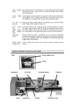
Bench lathe maintenance 

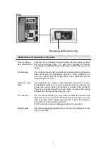
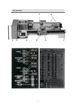
Identification and Description of the parts of the BV20-BL Lathe 

Summary of Contents for BL200L

Page 1: ...N Index of Contents BENCH LATHE BL200L BV20L OPERATION MANUAL ...

Page 2: ...utions These machines are supplied with a mould 13 Arnp Plug and 3 core power cable Before using the machine inspect the cable and the plug to make sure that neither are damaged If any damage is visible have the machine inspected repaired by a suitably qualified person If it is necessary to replace the plug it is preferable to use an unbreakable type that will resist damage Only use a 13 Arnp If e...

Page 3: ...holes to allow for bolt fixing Set out the centers of the holes as follows sizes are minimum excepting distance between centers From the left side of the bed Headstock side 170mm 150mm from the front edge of the bed Distance between centers 650mm second hole again 150mmfrom front edge Bolt the lathe to the bed using M12 nuts bolts and washers Once the lathe is mounted remove the headstock cover pl...

Page 4: ... by the work piece it is horizontal to but not necessarily parallel with the lathe bed along its length Compound Axis This is the axis described by the compound slide when it is being operated independently of the traverse slide and the saddle Please take some time to identify the various parts of your machine so that you are familiar with the terminology we will use to enable you to set up and op...

Page 5: ...oling centers drill chuck reamers etc the barrel has a travel of 50mm this travel allows the mounted tool or centre to be brought into controlled contact with the work piece Mounting feet Shaped in the casting of the lathe bed the two feet have 14mm slots cut into them to enable the fitting of two 12mm bolts to effect the rigid fastening of lathe onto it s stand A work bench Lathe bed V rail and f...

Page 6: ... slide also lock the compound slide along its selected axis or 45 degrees from the main axis The compound slide fits over this vee slide mount the accuracy of the fit is maintained by the gybe strips set in the front edge of the compound slide There is a scale set on the front of the circular base to enable the angle set on the compound slide to be measured Compound slide control handle A U handle...

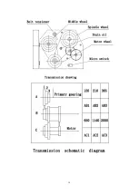
Page 7: ...t This chart indicates the necessary gears and their positions to enable the wide range of metric imperial module and diameter threads to be cut and the different feed rate to be achieved The feed speed is quoted as a linear distance along the Main Axis per revolution of the leadscrew Reversing switch Rocker switch set under a protective cover to prevent inadvertent operation changing the position...

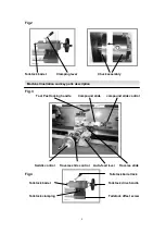
Page 8: ...king handle Compound slide compound slide control Saddle control Traverse slide control Auto feed lever Traverse slide Fig 4 Tailstock barrel lock Tailstock barrel Tailstock drive handle Tailstock clamping Tailstock offset screw Machine Illustration and key parts description ...

Page 9: ...ecured to the top of the headstock gearbox by four cap head bolts Unscrew the bolts and remove the cover to inspect the gearbox or replace or top up the oil There is no gasket beneath the cover plate so ensure the mating surfaces are clean before replacing the cover 18T reversing The 18T reverse tumbler gear when fitted enables the rotation of the leadscrew to be reversed For left hand threads as ...

Page 10: ...10 ...

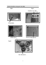
Page 11: ...11 Fig 8 Fig 9 Headstock cover plate Oil sight glass Oil drain plug Door for change gear box Fig 10 Machine Illustration and key parts description Door micro switch ...

Page 12: ...ides to spread the oil to all surfaces both hidden and visible 4 Spray up under the rack cover to lubricate the rack G 5 Apply oil to the change gears and their axle mountings H Daily Pre use 1 Clean all swarf and chips away from the machine bed slide surfaces and the tool post 2 Exercise the slide and ensure no swarf etc is lodged in the drive shaft tunnels 3 If you have been using suds make sure...

Page 13: ...13 D H E G A C F Oil Lubrication Identification and Description of the parts of the BV20 BL Lathe B ...

Page 14: ...14 ...
Reviews: