14
PANEL FUNCTION INSTRUCTION
ARC 400IT Front Panel Layout
1
Remote control switch
7
Current adjustment knob
2
VRD switch
8
ARC force adjustment knob
3
VRD indicator
9
Hot start adjustment knob
4
Abnormal indicator
10
Positive output terminal
5
Current meter
11
Remote control socket
6
Voltage meter
12
Negative output terminal
The images shown here are indicative only.
Summary of Contents for ARC 400IT
Page 1: ...ARC 400IT WELDING MACHINE USER MANUAL...
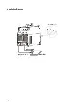
Page 12: ...12 Installation Diagram Power Supply Workpiece Earth Clamp Electrode Holder...
Page 20: ......
Page 21: ......

