background image


19


THERMISTOR TEST 


Thermistors vary their resistance value according to the temperature they detect. For example, at 
room temperature they have low resistance. When the temperature decreases, the resistance value 
increases. The following table shows the approximate readings based on a temperature scale. In 
fact, what is actually important about thermistors is that they must not show a reading of infinite 
value (open) or zero resistance (closed), and when they turn hot or cold their resistance value 
must vary. 
 
Thermistors located in the freezer and in the fresh food compartment must have the same 
characteristics and values; the difference stems from the type of connector and the temperature 
they use to send a signal to the board. 


TEMPERATURE RESISTANCE


TEMPERATURE RESISTANCE 

40 °C (104ºF) 

3,000 


5 ºC (41ºF) 

10,700 


35 °C (95ºF) 

3, 500 


0 ºC (32ºF) 

12,800 


30 °C (86ºF) 

4,100 

 -5 

ºC 

(23ºF)  16,000 


25 °C (77ºF) 

5,000 

 -10 

ºC 

(14ºF)  24,000 


20 °C (68ºF) 

6,000 

 -15 

ºC 

(5ºF)  34,000 


15 °C (59ºF) 

7,800 

 -20 

ºC 

(-4ºF)  45,000


10 ° C (50ºF) 

9,300


NOTE: 

THE VALUES BETWEEN EACH READING CAN VARY, BECAUSE THE 

THERMOMETER SENSES TEMPERATURE FASTER THAN THE THERMISTOR (SINCE 
THE THERMISTOR IS ENCAPSULATED). IF THE THERMISTOR IS KEPT AT A 
CONSTANT TEMPERATURE, THE RESISTANCE VALUE WILL BE HIGHER, BECAUSE 
BOTH THE THERMOMETER AND THE THERMISTOR TEMPERATURE WILL BE 
STABLE. 

 
COMPRESSOR OPERATING CYCLE 


When the electronic board sends a signal to enable the operating cycle of the compressor, both 
the potentiometer and the temperature sensor start operating to precisely regulate compressor 
operation and keep food at the desired temperature. When the potentiometer's knob is turned, this 
indicates to the sensor the temperature range under which the fresh food compartment must be 
kept and, at the same time, the sensor, based on this range, sends a signal to indicate the 
compressor's periods of operation and idleness. 

 
DEFROST CYCLE 


When the refrigerator is connected for the first time or after a long period of not using it, the 
electronic board will send a signal to enable the defrost cycle after eight hours of accumulated 
compressor operating time, depending on the time the resistance keeps connected during the 
defrost cycle (20, 30, 40 minutes).  


Summary of Contents for serviplus SEDNA ESTILO

Page 1: ...1 mabe SERVICE MANUAL FOR SEDNA ESTILO REFRIGERATORS from Mabe and G E PUB 06 MAN RE 02...

Page 2: ...2...

Page 3: ...AL DATA Electrical specifications No load operation Cooling unit Installation AIRFLOW Fan motors baffle lines ICE FACTORY Ice tray filling ice buckets ice disposal ELECTRONIC CONTROL BOARDS Deluxe ele...

Page 4: ...this technical manual is designed for technical personnel with knowledge and expertise in electricity electronics and mechanics as a guide for servicing these automatic no frost refrigerators Any pers...

Page 5: ...ment Follow these instructions 1 Start using your product keeping the factory preset positions medium level for both controls Let the appliance operate for 6 hours so that the temperature becomes stab...

Page 6: ...so see in the digital display an indicator light that swirls quickly This feature remains enabled for approximately an hour Once this period is over the refrigerator returns to normal operation Alarm...

Page 7: ...stem Forced Air Cooling Unit This kind of system uses fans in the freezer and the condenser area to remove the hot air from the condenser and the refrigerator area Natural Convection With Static Conde...

Page 8: ...ent consists of a bimetallic disc which when it detects an excessive temperature in the compressor or when its integrated resistance becomes too hot due to an excessive current bends and disconnects t...

Page 9: ...e its resistance when the temperature is higher The operating element of the PTC is basically a highly pure barium titanate disc with aluminum coating When a certain voltage is transmitted to the PTC...

Page 10: ...ID MID Control Position Room Temperature 70 F 90 F Fresh Food Compartment F Freezer F Compressor operation COOLING UNIT Refrigerant charge R134a 3 5 ounce 13 15 cubic foot models Compressor cooling ca...

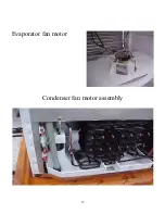
Page 11: ...ts AC The evaporator fan motor circulate the warmer air of the fresh food compartment through the evaporator and sends cold air to the freezer and fresh food compartments The condenser fan motor works...

Page 12: ...the resistance is connected and to program the next defrost cycle DEFROST SENSOR The sensor s function is to detect the amount of ice and time that the resistance is enabled in order to vary the time...

Page 13: ...13 Evaporator fan motor Condenser fan motor assembly...

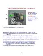
Page 14: ...CE UNPLUG IT FROM THE ELECTRICAL OUTLET C DISCONNECT THE WIRING HARNESS FROM THE FREEZER SENSOR CON1 D ENERGIZE THE APPLIANCE PLUG IT INTO THE ELECTRICAL OUTLET E AFTER APROX 4 SECONDS TURN ON THE COM...

Page 15: ...evaporator is low enough to have the Defrost Thermostat closed and allow current flow towards the Resistance F TO RE ENABLE THE COMPRESSOR OPERATION FOLLOW THE INSTRUCTIONS FROM STEP G G DE ENERGIZE...

Page 16: ...temperature control integrated to the board In case any of these components is damaged the whole assembly must be changed because each board is calibrated with these components When applying a 127 A C...

Page 17: ...200D2124G002 Main Board for 11 14 Models 220 V Polar Electronic with knob 200D2124G003 Main Board for 15 18 Models 110 V Polar Electronic with knob 200D2124G004 Main Board for 15 18 Models 220 V Polar...

Page 18: ...st points GND and P P which will turn off the compressor Three seconds later a signal will be sent to the defrost resistance to start working and at this moment the white and blue cables must give a r...

Page 19: ...TE THE VALUES BETWEEN EACH READING CAN VARY BECAUSE THE THERMOMETER SENSES TEMPERATURE FASTER THAN THE THERMISTOR SINCE THE THERMISTOR IS ENCAPSULATED IF THE THERMISTOR IS KEPT AT A CONSTANT TEMPERATU...

Page 20: ...t cycles will start after 48 hours of accumulated operating compressor time This feature is cleared by the board s integrated photocell when the fresh food compartment door is opened OPERATION TEST Se...

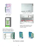
Page 21: ...sembly Airflow system Defrost system components are the thermostat the thermistor and the resistance heater Defrost drainage system The defrost duct is hidden behind the back and the insulating materi...

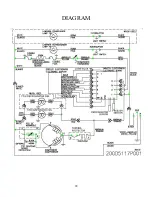
Page 22: ...22 DIAGRAM...

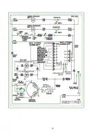
Page 23: ...23 LIGHT BLUE...

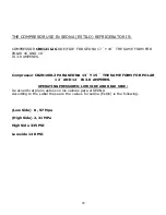
Page 24: ...PERES Compressor CBZN100L2 PARA SEDNA 13 Y 15 THE SAME FORM FOR POLAR 12 AND 14 IS 3 8 AMPERES OPERATING PRESSURES LOW SIDE AND HIGH SIDE De acuerdo al plano estos son los valores para el SEDNA Accord...

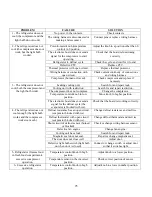
Page 25: ...ob to higher position 3 The refrigerator does not cool both the compressor and the light bulb work The electronic board does not send a signal for the defrost cycle the evaporator is blocked with ice...

Reviews: