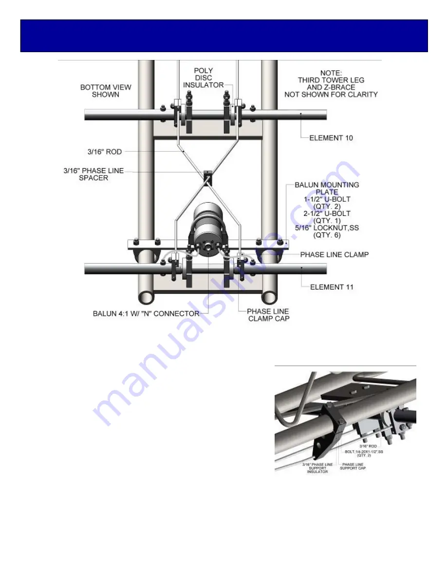
1. Mount the 4:1 BALUN MOUNTING PLATE assembly to the TOWER BOOM just behind element
#11 as shown above. Route the balun leads to the 1/4-20 x 1-1/2 bolts through the element butts
and tighten securely.
2. Locate the shortest pair of 3/16” rod phasing lines and slide
a 3/16” PHASE LINE INSULATOR onto the rods and feed
the front ends into the grooves in the PHASE LINE
CLAMPS. Hanging below the element butts. Slide the rods
far enough through to insert the other ends into the PHASE
LINE CLAMPS on element #10. Center and align the rods
so the bends are flat and parallel. Now tighten the front
PHASE LINE CLAMPS only.
3. Continue by adding the next set of phasing lines between
element #10 and #9. Center align the phasing rods and
tighten the PHASE LINE CLAMPS on element #10. Contin-
ue installing phasing lines and 3/16” PHASE LINE SPAC-
ERS to element #8.
4. The phasing lines between element #8 and #7 and beyond require (4) 3/16” PHASE LINE SUP-
PORT INSULATORS between each element. String on the 3/16” PHASE LINE SPACER and
then two 3/16” PHASE LINE SUPPORT INSULATORS from each end of the phasing lines. Posi-
tion the assembly under the boom and add the PHASE LINE SUPPORT CAPS. Use 1/4-20 x 1-
1/2” bolts that thread into 3/16” PHASE LINE SUPPORT INSULATORS. Tighten the bolts until no
rotation of the 3/16” PHASE LINE SUPPORT INSULATOR is possible. DO NOT OVERTIGHT-
EN.
6-30LP11 BALUN & PHASE LINE
Summary of Contents for 6-30LP11
Page 6: ...6 30LP11 ELEMENT ASSEMBLY 4 11...
Page 7: ...6 30LP11 ELEMENT ASSEMBLY 3...
Page 8: ...6 30LP11 ELEMENT ASSEMBLY 2...
Page 9: ...6 30LP11 ELEMENT ASSEMBLY 1...
Page 22: ...6 30LP11 PARTS IDENTIFICATION...


