RZMS-U9
5-2-55, Minamitsumori, Nishinari-ku, Osaka 557-0063 JAPAN
Phone: +81(6)6659-8201 Fax: +81(6)6659-8510 E-mail: [email protected]
EM-7602 Rev.11 P. 4 / 8
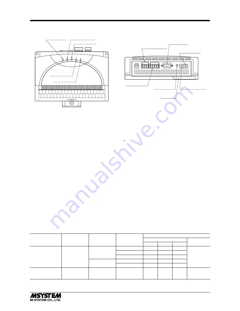
COMPONENT IDENTIFICATION
T1 T2 T3 T4
T5 T6 T7
1A 1B 1C 3A 3B 3C 5A 5B 5C 7A 7B 7C 9A 9B 9C 11A 11B
ALM
+
ALM
–
11C
2A 2B 2C 4A 4B 4C 6A 6B 6C 8A 8B 8C 10A 10B 10C 12A 12B 12C
TRG
+
TRG
–
RUN Indicator LED COMM Indicator LED
ERR Indicator LED
TRIG Indicator LED
ALM Indicator LED
RS-485 Connector
Configurator Jack
Node Address Setting
Rotary SW
Operating Mode
Setting Rotary SW
RS-232-C
9-pin Connector
Power / FG Terminals
■
TOP VIEW
■
REAR VIEW
Specifications
■
INDICATOR LED
RUN
:
Green LED blinks when the internal micro-
processor is operating normally.
COMM
:
Communication LED. Amber LED turns on
when the RZMS is receiving normal data
query frames from Modbus and sending re-
sponses out.
ERR
:
Error LED. Red LED turns on with internal
errors and blinks when the RZMS is receiv-
ing abnormal data query frames from Mod-
bus.
ERR LED may also blink while the PC Re-
corder is not recording, however, it is not an
abnormality or a failure of the RZMS as far
as the LED turns off when the PC Recorder
starts recording. (The RZMS blinks the ERR
when it receives a break signal from certain
types of PC designed to indicate an abnor-
mality when application programs are not in
use of one or more COM ports.)
TRG
:
Trigger LED. Amber LED turns on when the
trigger contact input turns on.
ALM
:
Alarm LED. Amber LED turns on when the
alarm contact output turns on.
■
NODE ADDRESS SETTING ROTARY SW
1 through F
: Setting at the power startup is recognized as
the module’s node address.
0
:
Setting with PC Configurator Software is
enabled. Software settings are deleted if the
RZMS is started up with a setting other than
zero (0).
■
OPERATING MODE SETTING ROTARY SW
A/D conversion mode, service channel numbers, cold junction compensation, line noise filter frequency and burnout action for
T/C and RTD input can be specified using this switch.
Setting with PC Configurator Software is enabled when the switch is set to zero (0), except that the cold junction compensa-
tion can be enabled/disabled for individual channels on the PC Recorder Software programs: MSR128LS and MSR128LV. In
order to protect the software setting before the power is turned off, be sure to turn the power supply on with ‘0’ setting.
1 through F
: Combination of settings as shown in the table below.
0
:
Last software setting before the power is turned off is enabled.
A/D
CONVERSION MODE
SERVICE
CHANNEL
NUMBERS
COLD JUNCTION
COMPENSATION
(T/C)
LINE NOISE FIL-
TER
FREQUENCY
BURNOUT (T/C and RTD)
All Channels
Individual
Channels
NONE
UP
DOWN
Medium
12
With
50/60 Hz
1
2
3
50 Hz
4
5
6
60 Hz
7
8
9
Without
50 Hz
A
B
C
60 Hz
D
E
F
Software setting for
all channels (Fast,
Medium, Slow)
Software setting
(12 or 6)
Software setting
for individual
channels
Software setting
for all channels
(50, 60, 50/60 Hz)
0
Software
setting
Note 1: Specifying the exact frequency (50 Hz and 60 Hz) provides better protection than 50/60 Hz setting.
Note 2: Factory setting is ‘1.’