


R3-NF3
5-2-55, Minamitsumori, Nishinari-ku, Osaka 557-0063 JAPAN
Phone: +81(6)6659-8201 Fax: +81(6)6659-8510 E-mail: [email protected]
EM-8288 Rev.2 P. 5 / 8
TRANSMISSION DATA DESCRIPTIONS
The DIP SW in the front of the module specifies I/O points, I/O type and with or without of I/O module status data setting.
I/O DATA is assigned data allocation setting from module 1 orderly.
The data of I/O module out of the setting area is invalid.
When there is I/O module status data, use the data area of the last 2 words of the input data area as the status data. When
the status data and I/O data overlap, the status data takes precedence.
For example, when the number of I/O points is “16” and SW1 and SW2 are set as shown below.
Slot 1
4
Slot 2
4
Slot 3
4
Slot 4
1
Slot 5
1
Slot 6
1
Slot 7
1
Then the I/O data are assigned as in the figures below:
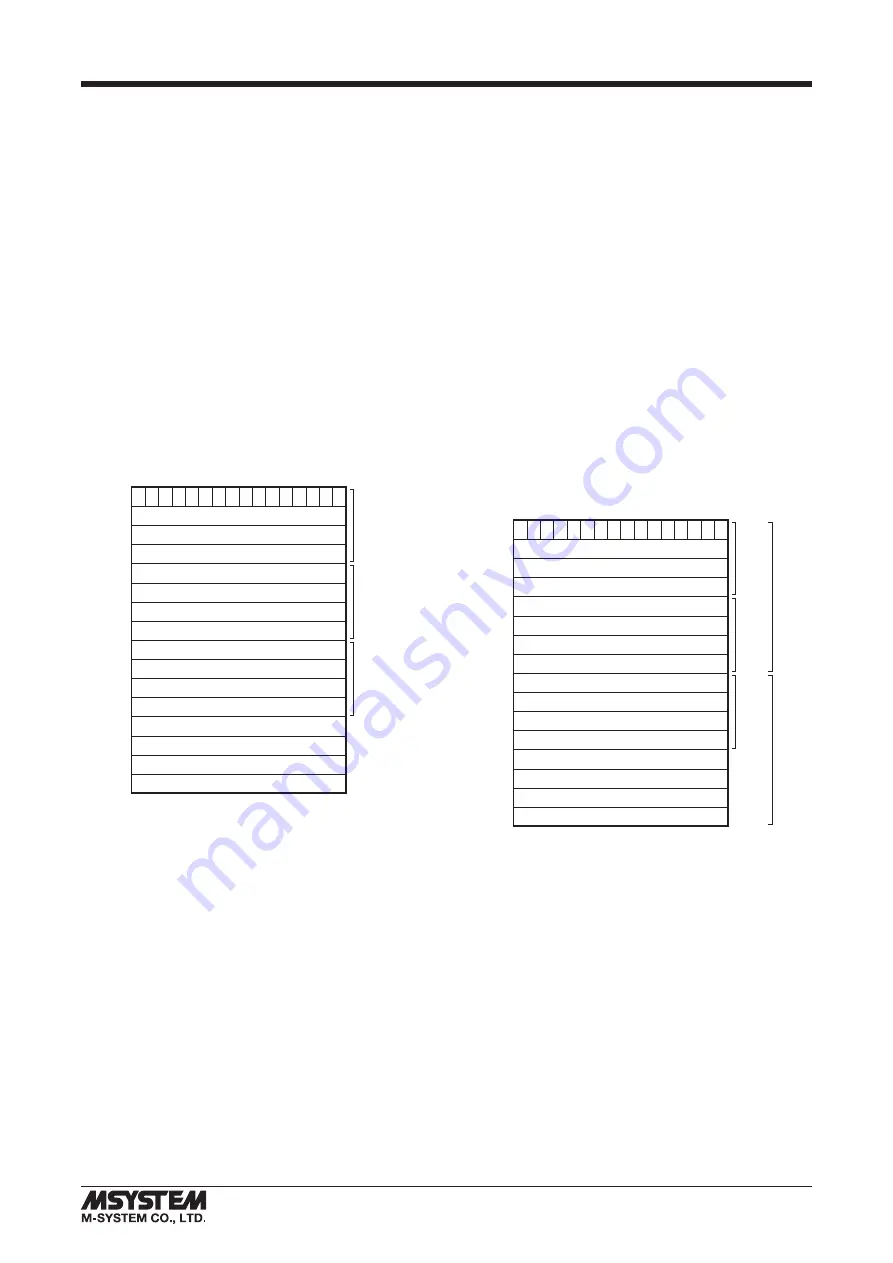
■
IN THE CASE OF NO I/O MODULE STATUS (KS3: OFF)
• I/O TYPE: INPUT ONLY or OUTPUT ONLY
The side DIP SW (SW1, 2) determine data allocation of
module (number of data) per module.
The number of data set by SW1 and SW2 is assigned to
transmission data in order from slot 1.
0
15
+0
+2
+4
+6
+8
+10
+12
+14
Slot 1
Slot 2
Slot 3
Slot 4
Slot 5
Slot 6
Slot 7
Begin
Address
• I/O TYPE: INPUT / OUTPUT MIXED
The number of input points and the number of output points
are assigned half numbers of KS0 to 1 respectively.
The first half of the data area is the input area and the sec-
ond half is the output area.
Please set the input module in slot 1 and 2, and output mod-
ule after slot 3.
0
15
+0
+2
+4
+6
+8
+10
+12
+14
Slot 1
Slot 2
Slot 3
Slot 4
Slot 5
Slot 6
Slot 7
Input
(8 points)
Output
(8 points)
Begin
Address


