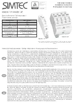
MD7PA
EM-8056 Rev.4 P. 4 / 5
■
CONNECTION DIAGRAM
PA BUS
5
2
6
3
7
8
DISCHARGE
ELEMENT
DISCHARGE
ELEMENT
4
1
Series Resistance
(SHLD)
Surge Side
Protected Side
Protected Device
M-RESTER
SHLD
FG
+
–
*
2
*
1
*
1. Choose the grounding (FG) when the shield wire is to be grounded.
*
2. When SHLD is not isolated from PA BUS, DO NOT connect the surge protector’s terminal 7 to SHLD.
*
3. Oxide film on the surface of an aluminium rail may lower the electric conductivity between this module and the ground.
Use a steel or copper rail.
*
4. Be sure to ground the DIN rail. Recommended grounding resistance max. 100 ohms.
*
5. Cross-wire from the DIN rail to the metal housing of the protected device to equalize the ground potential.
Ground only the surge protector when the protected device has no grounding terminal.
PA BUS
DIN RAIL ADAPTOR
(for grounding)
DIN RAIL
Grounding
*
3
*
4
Crossover Wire
*
5
■
NETWORK CONFIGURATION
Protected
Devices
(Nodes)
M-RESTER
G
G
G
G
G
G
G
Protected
Devices
(Nodes)
When the distance between nodes are relatively long (e.g. grouped and separated by cabinets),
install the MD7PA by each group of devices. Insert the MD7PA at the surge side of the network.
For detailed information on the network, refer to that provided by PROFIBUS International.
*
1. Fieldbus devices complying with IEC 61158-2 operate by a supply voltage between
9V and 32V DC.
Take the MD7PA’s internal series resistance into consideration when determining the
cable distance if there is a large current flow on the bus line.
Crossover Wire
Crossover Wire
*
1
M-RESTER
056 222 38 18
www.sentronic.com
SENTRONIC
AG